
Grantee Research Project Results
Final Report: Development of Mobile Self-Powered Sensors for Potable Water Distribution
EPA Grant Number: R834868Title: Development of Mobile Self-Powered Sensors for Potable Water Distribution
Investigators: Banks, M. Katherine , Brovont, Aaron D , Salim, Amani , Porterfield, Marshall , Wu, Ruoxi , Pekarek, Steve , Jefferson, Travis
Institution: Purdue University
EPA Project Officer: Page, Angela
Project Period: January 1, 2011 through December 31, 2013 (Extended to December 31, 2014)
Project Amount: $599,997
RFA: Advancing Public Health Protection through Water Infrastructure Sustainability (2009) RFA Text | Recipients Lists
Research Category: Drinking Water , Water
Objective:
A mobile sensor system is being designed and fabricated for water quality monitoring in a potable water distribution system. The research being conducted is focused on the areas of 1) sensor research and device fabrication, 2) application testing of water quality sensors and 3) wireless mobile sensor networking. Significant progress has been made in all three areas.
Summary/Accomplishments (Outputs/Outcomes):
In this final year’s effort, the focus was placed primarily on the analysis and design of the energy conversion system for the mobile sensor. Prior to describing this effort in detail, a status summary of what was accomplished under the overall research project is described. The status summary is described along the lines of (1) MAB design, (2) packaging design and fabrication, and (3) integration with electronic components, (4) electronic control system, and (5) energy conversion.
Sensor research and device fabrication
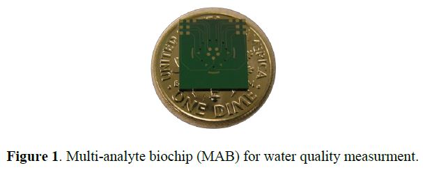
Overall, within this project a multi-analyte biochip (MAB) system was designed that consists of multiple ion-selective electrodes that are microfabricated on a silicon substrate. Potentiometric measurements in the millivolt range are recorded. The sensor is calibrated based upon a lab experiment, and the concentrations of target analytes are determined from calibration curves taken for a respective sensor. Within the project, ion-selective electrodes were made that are selective for H+, NH4+, Ca2+, Cl-, and CO32- ions, which are the key ions for pH, water hardness, and disinfectant. Also, lifetime tests of the sensor were performed where calibration slopes for H+ were recorded over extended periods of time (10 days). A representative MAB is shown in Figure 1.
MAB design: The MAB design consists of six ion-selective-electrodes (ISEs) (Φ = 240 μm). All six of these electrodes are working electrodes (WEs) for potentiometric sensing, with three WEs sharing one Ag/AgCl reference electrode (RE) (Φ = 480 μm). The biochip also houses three WEs each having its associated pseudo-reference electrode for amperometric sensing. All WEs and REs are located within a microfluidic chamber 6 mm in diameter. The overall biochip dimension is 10 x 11 mm.
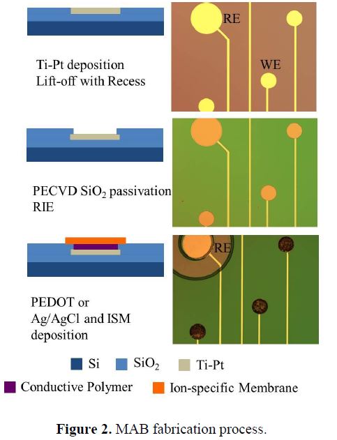
MAB fabrication: Fabrication of the first generation MAB, which was developed in the initial years of the project efforts, started with a silicon oxide wafer that is patterned with Ti/Pt electrodes of 30/150 nm respectively via lift off. Electrode areas were passivated with oxide, exposing only the area of the active WEs. Then, the conductive polymer poly(3,4-ethylenedioxythiophene)-poly-(styrenesulfonate) (PEDOT:PSS) was deposited via cyclic voltammetry at a scan rate of 20 mV/sec on the active WEs1, followed by deposition of the ion-selective membrane (ISM) selective for specific analytes of interest via spin-coating at 1,500 rpm. The ISM was dried in a desiccator overnight to remove unwanted solvents. An Ag/AgCl ink was deposited on reference electrode areas. Finally, 3 the MAB was conditioned in ISM conditioning solution3,4 that helps establish a stable potential at the ISM interfaces.
In the second generation MAB, which represents the final stage achieved under this project, the fabrication process was further refined by replacing the PEDOT:PSS WEs with Ag/AgCl and depositing a thinner ISM (e.g., drop-coating VS spin-coating) on the WEs. This is to ensure a faster response time (e.g., 1 min vs 5 min) and simplified the fabrication process (e.g., no electrochemical deposition of PEDOT:PSS is required). Additionally, a UV curable epoxy (Su8) was fabricated on the MAB to hold the O-ring in place to prevent leakage. Furthermore, the Ag/AgCl layer on the RE was deposited via a chloriding bathing process in 4% sodium hypochlorite rather than using a Ag/AgCl ink. This was done by depositing an extra layer of Ag on top of the Pt of the working and reference electrodes. The detailed fabrication process is shown in Figure 2 for both the first and second generations.
ISM Materials: All reagents and chemicals were of analytical grade, were obtained from Sigma Aldrich (St. Louis, MO, USA), and were used without further purification, including, hydrogen ionophore I (H+ I), tridodecylmethylammonium chloride (tDMACl), potassium tetrakis(4-chlorophenyl)borate (KTCPB), high-molecular-weight polyvinyl chloride (PVC), bis (2-ethylhexyl) sebacate (DOS), polyurethane spheres (PU), cyclohexanone (selectophore grade) (CHX), 3,4-ethylenedioxythiophene (EDOT) monomer, and sodium polystyrene sulfonate (NaPSS).
ISM preparation: The quantities of the various membrane components of the ISM are based upon the desired percentage for each and were calculated for a total weight of 500 mg. For the HISE membrane2,3, PU [9.9 wt %] was dissolved in CHX [10% wt/vol]. Once the PU spheres were dissolved, PVC [23.1 wt %], KTCPB [0.5 wt %], DOS [65.5 wt %], and H+ I [1 wt %] were added to the PU/CHX mixture. PU was used in conjunction with PVC to increase the mechanical stability and adhesion of the ISM to the biochip surface4,5. All ISM solutions were left under constant stirring overnight to ensure proper mixing of membrane components. The final recipe of all ISMs are shown in Table 1.
Table 1.Composition of the ion-selective membrane structure.
Ion-Selective-Membrane |
Structure Composition | Reference |
|---|---|---|
| H+ | 1.0 wt% hydrogen ionophore I 0.5 wt% potassium tetrakis(4-chlorophenyl)borate 65.5 wt bis(2-ethylhexyl) sebacate (DOS) 23.1 wt% poly(vinyl chloride) high molecular weight 9.9 wt% polyurethane |
[2, 3, 4] |
| Ca2+ | 1.00 wt% calcium ionophore II 0.60 wt% potassium tetrakis(4-chlorophenyl)borate 65.60 wt% bis(2-ethylhexyl) sebacate (DOS) 22.96. wt% poly(vinyl chloride) high molecular weight 9.84 wt% polyurethane |
[5, 7, 8] |
| CI- | 1.0 wt% chloride ionophore IV 0.6 wt% tridodecylmethylammonium chloride 65.4 wt% 2-nitrophenyl octyl ether (o-NPOE) 23.1 wt% poly(vinyl chloride) high molecular weight 9.9 wt% polyurethane |
[9] |
| NH4+ | 1.00 wt% ammonium ionophore I 66.80 wt% bis(2-ethylhexyl) sebacate (DOS) 22.54 wt% poly(vinyl chloride) high molecular weight 9.66 wt% polyurethane |
[6] |
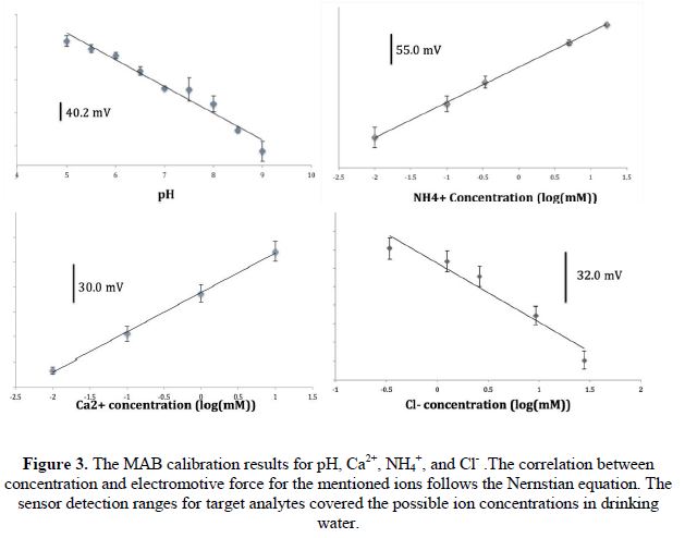
Sensor calibration: Within the project, ion-selective electrodes for the MAB were made for H+, NH4+, Ca2+, Cl-, and CO32- ions, which are the key ions for pH, water hardness, and disinfectant. Representative calibration slopes are shown in Figure 3. All calibration slopes are Nernstian, meaning the sensor is able to detect concentration of selected analytes.
The lifetime of the MAB sensor was tested for the pH ion-selective electrode. After a MAB was conditioned, continuous introduction of samples of pH 6.3-8.3 was repeated from the first day. The drifted slope (voltage signal change detected over 1 unit of pH change) data is shown in Figure 4. Significant signal drift was not found until the eleventh day of testing. From this experiment, it is the present conclusion at end of this project, that the existing MAB sensor is reliable for at least 10 days after conditioning and calibration.
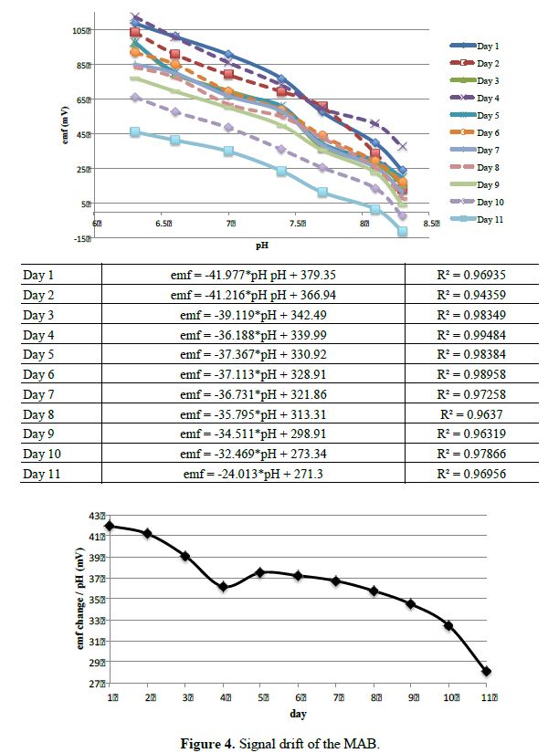
Table 2 compares the mobile sensor developed in this project to five models of EPA approved pH/ion sensor for water quality monitoring10. These water sensors used in field tests are ion-selective-glass based probe sensors. They need a bulky battery and several fragile glass probes for analyte detection. In contrast, the mobile sensor is lightweight and can be miniaturized, which is essential for mobility within a water distribution system. In addition, the pH sensitivity and detection limit of this mobile sensor are sufficient for the drinking water sample monitoring.
Table 2. A comparison of the final mobile sensor device over several multifunction sensors for water quality monitoring
| This Project | Weight (g) | Size (mm) | lower pH detection limit | lower pH detection limit | pH sensitivity |
|---|---|---|---|---|---|
| MAB chip | 0.2 | 11*10*0.2 | 5 | 9 | 0.1 |
| Mobile Sensor | 267.2 | 70.1 diameter | |||
| Model of Multifunction Sensor for Water Quality Modeling | |||||
| Hach/GLI Model P53 pH/ORP Analyzer [11] | 1600 | 150*144*142 | -2 | 14 | 0.01 |
| YSI 6600 [12] | 3180 | 498(549)*89*89 | 0 | 14 | 0.02 |
| YSI 6920DW [12] | 1700 | 464*74*74 | 0 | 14 | 0.02 |
| Hydrolab DS5 [13] | 3350 | 584*89*89 | 0 | 14 | 0.2 |
| Troll 9000 [14] | 1900-2700 | 473(610)*45*45 | 0 | 14 | 0.02 |
Packaging design and fabrication
The final generation mobile sensor was a 2.76 inch diameter spherical shell containing a MAB sensor, microfluidics, an electronic control system, and energy harvest system. The mobile sensor size was chosen for operation and movement in a water distribution pipe with a minimum diameter of 4 inches. Most water distribution pipes range in size from 4-inch to 36-inch nominal diameters.
The mobile sensor consists of two hemispheres as shown in Figure 5: the sampling hemisphere and the energy/electronics hemisphere. Each hemisphere was designed to segregate the internal components by function and secure them in place. The packaging is waterproof to protect vulnerable equipment from the outside environment, and the two hemispheres are sealed together with a Viton gasket.
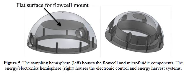
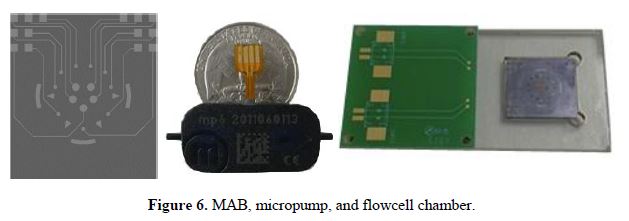
The sensor packaging was designed using commercially available CAD software (SolidWorks 2013 x64 Edition). The sampling hemisphere consists of a flow cell chamber housing the MAB, which is a replaceable cartridge, and microfluidic components. The flow cell is connected via microtubing to an MP6 micropump (pumping rate of 160 μL per minute at a power of 200 mW). The micropump furnishes a water sample from the environment to the MAB. The MAB contact pads are wire-bonded to a printed circuit board (PCB) that is connected to the electronic control system in the opposite hemisphere via jumper cables. The flowcell chamber housing the MAB is constructed of clear acrylic material so that it will not interact with the chemicals in the water sample. The sensing chip is placed inside the flow cell with a gasket, where all working and reference electrodes are immersed in the sampled liquid. The flowcell cartridge with the MAB is relatively simple to remove from the package for calibration or replacement. The MAB, micropump, and flow cell cartridge are shown in Figure 6.
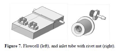
The flowcell chamber, modeled in Figure 7 (left), was custom built by laser cutting and joining acrylic pieces with pressure-sensitive adhesive (PSA). The advantage of this design is the reduced size and convenience of calibration with the simplified signal cable connector. Samples are conducted into and out of the device through ports and tubing connected with rivet nuts, shown in Figure 7 (right). The dimension and size of the tubing and rivet nuts are chosen to fit the shape and thickness of the sensor package.
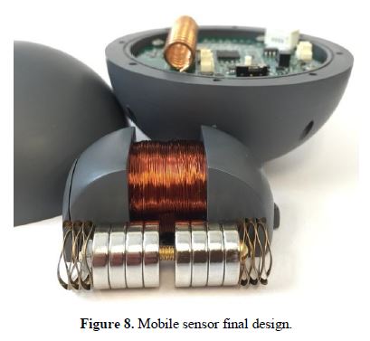
The energy/electronics hemisphere consists of an electronic control system PCB and an air-core tubular permanent-magnet generator, dubbed the energy harvest system. The final integrated device is shown in Figure 8. In the final assembly, the flowcell cartridge and energy harvest system was glued in place while the electronic control system PCB was secured with screws. All remaining components were affixed with glue or pressure-sensitive adhesive (PSA).
Integration with electronic components
The electronic control system was designed to coordinate all device activity, read measurements from the MAB, and transmit data to remote base stations with the lowest possible energy consumption. A Texas Instruments (TI) CC430 microcontroller with integrated RF transceiver is the core around which the whole system is built. Its suite of peripheral devices, ultra-low power consumption, and minute footprint make it an ideal choice for the MAB-based water sensing application. As part of the project, software was developed for this platform to execute all necessary data acquisition, logging, and transmission functions.
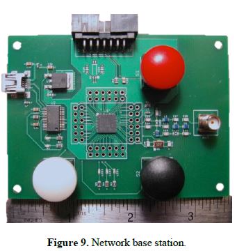
For wireless mobile sensor networking, a network base station was designed to receive data from the mobile sensors and relay the data back to a control network or PC for monitoring and data logging. A base station prototype was designed and constructed as shown in Figure 9. Wireless communication between the base station and mobile sensors was achieved during the project, and a graphical user interface was developed for viewing and logging data on a local PC. Details are provided in subsequent sections.
Electronic Control System
The electronic control system on the mobile sensor is divided into three subsystems in the final generation design: digital, analog, and power. The digital subsystem consists of the CC430 microcontroller with integrated wireless transceiver, an external memory module, and the pump controller. The analog subsystem comprises an INA333 instrumentation amplifier to interface with the MAB sensor and a voltage reference for compatibility with the digital subsystem. The power subsystem is itself divided into three distinct systems: energy harvest, battery charging and protection, and voltage regulation. The final digital, analog, and power subsystems are described in detail in the following sections.
Digital subsystem: The digital subsystem has two main objectives, data acquisition and wireless communication, which are largely achieved through the native capabilities of the CC430 microcontroller. The other components of the digital subsystem, the external memory module and the pump controller, expand these capabilities to handle the specific needs of the mobile sensor application.
The Real-Time Clock on the CC430 coordinates all of the activities for data acquisition. The sampling rate is user-specified and is presently configured for two-minute intervals. At the beginning of each data acquisition cycle, the pump is enabled and runs for a user-designated time period (presently 30 seconds). The pump turn-on/off is controlled by another of the CC430’s timer peripherals. The remainder of the sampling interval is a hold period to allow the MAB voltage to stabilize. At the conclusion of the cycle, the MAB terminal voltage is measured via the on-chip analog-digital converter (ADC) and stored locally along with a timestamp. Each sample requires seven bytes of memory, which is allocated dynamically at the time of sampling. The storage of the data sample completes the acquisition process, and the sampling cycle begins anew. As noted previously, the sampling rate and all timing intervals can be adjusted in software to meet the required settling times for the various MAB sensor architectures.
Once water quality data has been acquired on a mobile sensor, it must be transferred to a base station for monitoring and analysis. This is accomplished wirelessly by transmitting and receiving a sequence of control packets followed by a data payload and a checksum to ensure a valid transmission. In this application, a data “packet” comprises the seven bytes required for each sample, two for the voltage reading, three for the timestamp, and one each for a packet type identifier and a checksum for data handling purposes. The operational characteristics of the base station and the mobile sensor differ significantly; the mobile sensor is designed to transmit data payloads while the base station receives them. In short, the transmission scheme is a sequential relay of control packets: ready signal, device identification signal, data ready signal, data payload, checksum.
Data transfer from a mobile sensor to a base station is controlled by a ping timer on the base station, which is currently set in software for a two second period. On each ping, the first step in data transmission is attempted, a process known as handshaking. To begin the handshaking process, the base station broadcasts a ready signal, which indicates that it is ready to accept data. The mobile sensor is silent until this signal is detected. Upon detection, the sensor sends back a signal which uniquely identifies itself to the base station. The identification of each mobile device allows for a base station to communicate securely with a single mobile sensor regardless of the number of sensors within range. Once the base station selects a particular mobile sensor, a packet is sent back granting permission to that device to send data packets, completing the handshaking process. The sensor responds by sequentially transmitting and deleting each stored sample. It is noted that each data packet is validated by the base station, which notifies the sensor of a successful transmission before the data is deleted there. Data transmission continues with a single device until the samples are all transmitted successfully or an invalid packet is encountered. The ping timer is disabled during this handshaking process to allow for the possibility that an entire ping interval might transpire during a single transmission, although current operation appears to be much more rapid than the two-second interval. Once the data transmission terminates, the ping timer is re-enabled and the process begins anew.
Within the project, the data acquisition system and wireless communication designs highlighted in the previous paragraphs have been successfully designed and tested. As part of the design effort, an external memory module was included to lift the memory constraint set by minimal on-chip CC430 SRAM. This enables one to store data in the event that sensor-base communication is not possible or is only possible at long time intervals. To this end, a 64 kilobit (8192 bytes) FRAM chip was used and provides storage space for 1170 full seven-byte samples. The FRAM chip is controlled with an SPI communication bus, which is an included peripheral on the CC430 package.
Analog subsystem: The analog subsystem provides the necessary signal conditioning to interface the MAB with the digital subsystem. The design objective for this interface was to maximize the resolution of the MAB output while satisfying the input requirements for the ADC, which is complicated by the unusual electrical characteristics of the MAB. The MAB has a very large output impedance, which makes the choice of amplifier critical (and challenging). Texas Instruments’ INA333 instrumentation amplifier was selected for this purpose due to its very high input impedance, low power consumption, rail-to-rail operating range, and small footprint. Together with the LPV511 op-amp employed as a voltage reference, the INA333 amplifies and offsets the floating, differential output voltage of the MAB. In the first hardware revision, three amplifier designs were constructed and tested. The basic functionality of the three designs was verified, and one design was selected for its simplicity and superior noise immunity. Additionally, it was determined that to achieve the design objective of maximum output resolution, the gain of the amplifier must be calibrated for the particular MAB sensor in use. This is achieved in the final generation design through the inclusion of a potentiometer, which permits the INA333 a variable gain.
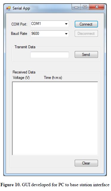
Base station to PC data transfer: The network base station has two main objectives: wireless communication with the mobile sensors and the relaying of data to a network PC or other external controller. As stated for the mobile sensors, wireless communication is handled natively on the CC430 microcontroller. The main challenge to wireless communication will be to determine the effective distance over which the mobile sensors and base stations will be able to consistently communicate due to water, metals, and other unknown conductive media obstructing the path of communication. This challenge will 13 be addressed in the next stage of testing. The main design consideration for the base station was the interface with a PC or other external controller. To facilitate this interface, a circuit was selected to incorporate an FT232R USB to UART converter, which will allow communication with the base station through a standard USB connection. Permanent data logging may then be handled by a network PC, enabling a simple interface for monitoring and analyzing data. To this end, a graphical user interface (GUI) has been developed to receive and log data on a PC attached locally to a base station. A screenshot of the GUI is shown in Figure 10. This GUI provides a simple means to display the data for viewing or to store the data in a column, tab-delimited text format. Once stored, the data may be imported into a spreadsheet application for further analysis or manipulation.
Power subsystem: As part of the research effort, a power subsystem was designed that includes three internal systems: energy harvest, battery charging and protection, and voltage regulation. The first of these is the energy harvest system. Initially, this system was designed assuming that energy would be harvested from impacts with the pipe wall. Based upon this assumption, two studies were performed in tandem to inform the design of the energy harvest system. The first study was a multi-objective optimization study with the goal of maximizing energy harvested per impact while minimizing the overall device radius. As part of this research, it was found in comparing the power needed for regular sampling with the expected harvesting capabilities for the desired device radius, that the energy harvest system should instead be a supplementary source responsible for recharging the primary energy source (i.e., a battery). The second design stage was a single-objective optimization study to maximize energy harvest subject to the actual shell dimensions and spatial constraints of the final generation packaging.
The second section of the power subsystem is the battery charging and protection circuitry. The objectives of this system are to regulate the capacitor voltage on the output of the energy harvest system and to charge the battery while preventing over-charging or over-discharging the battery. The battery for this system was selected to be a single-cell, 240 mAh, Lithium-ion-polymer battery, which has a nominal 3.7 V open-circuit voltage. The constraints for this cell are a maximum charge rate of 1 C, a maximum discharge rate of 0.5 C, and upper and lower voltage bounds of 4.2 V and 2.7 V, respectively. In this system, a comparator monitors the voltage on the output capacitor of the energy harvest system. When this voltage rises above a given threshold (5.7 V) the buck converter operates to move charge from the capacitor to the battery. Another set of comparators monitor the battery voltage to prevent charging when the battery voltage is too high and to prevent discharging when the battery voltage is too low by shutting down the voltage regulator and all downstream components. It is noted here that the FRAM chip in the digital subsystem is non-volatile so that data will not be lost in the event of a low-voltage shutdown.
The third section of the power subsystem is the voltage regulator. This section consists mainly of Texas Instruments’ TPS63031 fixed-output 3.3V Buck-Boost converter chosen for its high efficiency, small footprint, and shutdown feature. A SPDT sliding switch 14 toggles the shutdown pin of the converter between control by the battery protection circuitry and an OFF state.
Power Subsystem-Final Year
Within the final year of the contract, a focus was placed on validating the models utilized for the energy harvest system design and further advancing the energy harvest process. Toward this goal, the energy harvest system was tested in the laboratory. Hardware results were then compared with those predicted by the model. In addition, alternative designs for the energy harvest system were explored in which energy was extracted from rolling (rather than impact). Both of these efforts are described in detail in papers that were written this year. Rather than detailing in this report, they are provided as supporting documents. One of the key results of this study is that it would require many impacts/second to approach the same energy harvested as obtained from rolling. Therefore, it is suggested that if there is a desire to utilize energy harvesting, future water sensors should be configured for rolling.
Conclusions:
Overall, under this program a MAB-based water sensor was developed to detect H+, NH4+, Ca2+, Cl-, and CO32- ions in potable water systems. Key results include that the sensors developed follow a Nernstian calibration slope, meaning the sensor is able to detect concentration of selected analytes. The sensors have been tested for repeatability and to date have achieved similar voltage/concentration levels for up to 10 days. The time needed to process a sample was reduced from several minutes to less than a minute. Additional research is needed to bring this processing time down so that water can be sampled quickly. If the timing cannot be reduced, additional sensors are required to improve geographical resolution of the sampling.
The MAB was placed within a sensing sphere that included the processing circuits needed for on-line data storage, wireless communication, and energy harvest. Software was developed to coordinate communication between sensors and a central base station. The wireless sensing system utilized FM frequencies to help ensure sufficient signal strength over appreciable distances. The distance over which effective communication can occur was not tested. In free-space, the range of the CC430 transceiver is approximately 100 m or so, depending on the quality of circuit construction.
To reduce maintenance, an energy harvest system was designed, constructed, and tested. More importantly, the models necessary to obtain expected harvest/sensor volume were derived. These were used to obtain optimal energy harvest geometries. Moreover, they were used to show that rolling-based energy harvest is preferred over impact-based harvest. As a result, it is suggested that in future sensor systems, the sensors be designed with the intent to roll through the piping system.
Going forward, the next logical step would be to test the sensor system within an EPA testbed. Initial inquiries were made to the Cincinnati office to gauge testbed availability. It appears that there are some testbeds that could be made available if there is further interest. In addition, the mobile sensor system could be considered for alternative detection needs, such as the locating of leaks within piping systems. The sensor system could also be adapted for testing in open-water lakes, oceans, or streams.
References:
- D. S. Sakong, M. J. Cha, J. H. Shin, G. S. Cha, M. S. Ryu, R. W. Hower and R. B. Brown, Sensors and Actuators B-Chemical, 1996, 32, 161-166.
- D. Liu, M. E. Meyerhoff, H. D. Goldberg and R. B. Brown, Analytica Chimica Acta, 1993, 274, 37-46.
- N. H. Kwon, M. S. Won, D. S. Park and Y. B. Shim, Electroanalysis, 2005, 17, 641-647.
- S. Anastasova-Ivanova, U. Mattinen, A. Radu, J. Bobacka, A. Lewenstam, J. Migdalski, M. Danielewskic and D. Diamond, Sensors and Actuators B-Chemical, 2010, 146, 199-205.
- A. Bratov, N. Abramova, C. Domı́nguez, A. Baldi, Ion-selective field effect transistor (ISFET)-based calcium ion sensor with photocured polyurethane membrane suitable for ionised calcium determination in milk, Analytica Chimica Acta 408 (2000) 57-64.
- M.S. Ghauri, J.D.R. Thomas, Evaluation of an ammonium ionophore for use in poly(vinyl chloride) membrane ion-selective electrodes: solvent mediator effects, Analyst 119 (1994) 2323-2326.
- M. Maj-Zurawska, M. Rouilly, W.E. Morf, W. Simon, Determination of magnesium and calcium in water with ion-selective electrodes, Analytica Chimica Acta 218 (1989) 47-59.
- M. Otto, J.D.R. Thomas, Model studies on multiple channel analysis of free magnesium, calcium, sodium, and potassium at physiological concentration levels with ion-selective electrodes, Analytical Chemistry 57 (1985) 2647-2651.
- M. Rothmaier, W. Simon, Chloride-selective electrodes based on mercury organic compounds as neutral carriers, Analytica Chimica Acta 271 (1993) 135-141.
- EPA, “Distribution System Water Quality Monitoring: Sensor Technology Evaluation Methodology and Results: A Guide for Sensor Manufacturers andWater Utilities,” 2009, EPA/600/R-09/076.
- GLI International, Inc., Operating Instruction Manual of Hach/GLIModel P53 pH/ORP Analyzer, 2001, Rev. 7-1201.
- YSI. Inc., 6-Series Multiparameter Water Quality Sondes User Manual, 2011. 11, Rev. H.
- Hach Company, Hydrolab DS5X, DS5, and MS5 Water Quality Multiprobes User Manual, 2006. 02, Edition 3.
- In-Situ Inc., Multi-Parameter TROLL 9000, WQP-100 Operator’s Manual, 2005, rev. 010 09/05.
Journal Articles on this Report : 3 Displayed | Download in RIS Format
| Other project views: | All 15 publications | 3 publications in selected types | All 3 journal articles |
|---|
| Type | Citation | ||
|---|---|---|---|
|
|
Brovont AD, Pekarek SD. Optimizing air-core permanent-magnet-based energy harvest in free-rotating devices. IEEE Transactions on Energy Converson 2015;30(4):1621-1629. |
R834868 (Final) |
Exit |
|
|
Howard RA, Xiao Y, Pekarek SD. Modeling and design of air-core tubular linear electric drives. IEEE Transactions of Energy Conversion 2013;28(4):793-804. |
R834868 (2013) R834868 (Final) |
Exit |
|
|
Wan Salim WWA, Zeitchek MA, Hermann AC, Ricco AJ, Tan M, Selch F, Fleming E, Bebout BM, Bader MM, Ul Haque A, Porterfield DM. Multi-analyte biochip (MAB) based on all-solid-state ion-selective electrodes (ASSISE) for physiological research, Journal of Visualized experiments: JoVE 2013;74:50020. |
R834868 (2013) R834868 (Final) |
Exit |
Supplemental Keywords:
Contamination, drinking water, sensors, water distribution system, potable water distribution, security of drinking water system;Progress and Final Reports:
Original AbstractThe perspectives, information and conclusions conveyed in research project abstracts, progress reports, final reports, journal abstracts and journal publications convey the viewpoints of the principal investigator and may not represent the views and policies of ORD and EPA. Conclusions drawn by the principal investigators have not been reviewed by the Agency.