
Grantee Research Project Results
2012 Progress Report: Development of Mobile Self-Powered Sensors for Potable Water Distribution
EPA Grant Number: R834868Title: Development of Mobile Self-Powered Sensors for Potable Water Distribution
Investigators: Pekarek, Steve , Banks, M. Katherine , Porterfield, Marshall , Wu, Ruoxi , Salim, Amani , Brovont, Aaron D
Current Investigators: Banks, M. Katherine , Brovont, Aaron D , Salim, Amani , Porterfield, Marshall , Wu, Ruoxi , Pekarek, Steve , Jefferson, Travis
Institution: Purdue University
EPA Project Officer: Page, Angela
Project Period: January 1, 2011 through December 31, 2013 (Extended to December 31, 2014)
Project Period Covered by this Report: January 1, 2012 through December 31,2012
Project Amount: $599,997
RFA: Advancing Public Health Protection through Water Infrastructure Sustainability (2009) RFA Text | Recipients Lists
Research Category: Drinking Water , Water
Objective:
A mobile sensor system is being designed and fabricated for water quality monitoring in a potable water distribution system. The research being conducted is focused on the areas of 1) sensor research and device fabrication, 2) application testing of water quality sensors and 3) wireless mobile sensor networking. Significant progress has been made in all three areas.
Progress Summary:
In sensor research and device fabrication, a multi-analyte biochip (MAB) system has been designed that consists of multiple ion-selective electrodes that are microfabricated on a silicon substrate. Potentiometric measurements in the millivolt range are recorded. The sensor is calibrated based upon lab experiment, and the concentrations of target analytes are determined from calibration curves taken for a respective sensor. To date, ion-selective electrodes have been made that are selective for H+, NH4+, Ca2+, Cl-, and CO32- ions, which are the key ions for pH, water hardness, and disinfectan . A MAB is shown in Figure 1.
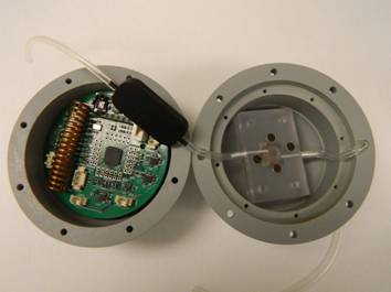
Figure 7. The MAB calibration results for pH, Cl-, NH4+, and Ca2+. The correlation between concentration and electromotive force for the mentioned ions follows the Nernstian equation. The sensor detection ranges for target analytes covered the possible ion concentrations in drinking water.
As mentioned previously, mobile sensor electronic control system and network base station prototypes have been designed and constructed. The main design considerations for both prototypes are presented in greater detail in the following paragraphs along with the results of the initial hardware validation. The mobile sensor electronic control system has three main objectives: data acquisition, temporary data logging, coordination of pump activity, and wireless transmission of data to a base station. The primary design challenge for data acquisition in the mobile sensors is the interface of the MAB with the analog-to-digital converter (ADC) on the microcontroller. The design objective for this interface is to maximize the resolution of the MAB output while satisfying the input requirements for the ADC, which is complicated by the unusual electrical characteristics of the MAB. The MAB has a very large output impedance, which makes the choice of amplifier critical. Therefore, three different circuits were designed based on Texas Instruments’ INA333 instrumentation amplifier to properly condition the output of the MAB.
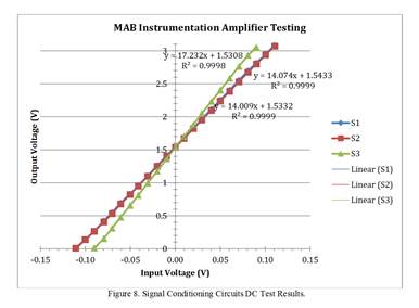
It was desirable that all three circuits be implemented in the first prototype in order to compare the results from each circuit and investigate the impact of the interface circuit on the data collected. The INA333 was chosen for its very high input impedance, low power consumption, rail-to-rail operating range, and small footprint. The operation of the three signal conditioning circuits has been tested and verified. A simple DC input to the circuits was supplied, and the output was recorded and compared to expected results. The results are displayed in Figure 8.
In the results shown above in Figure 8, all three signal conditioning circuits on the mobile sensor prototype board were connected to a floating DC source. The source voltage was then stepped from -100 mV to 100 mV by 10 mV intervals. The input and output voltages of each circuit were recorded at each operating point. Expected results were calculated from the voltage transfer function of each circuit using the nominal component values. Error was calculated at each point by the following equation. :
Error = [(Vactual - Vexpected)/ Vexpected] X 100%
The average error for the circuit was expected to be less than or equal to 5% as those are the manufacturing tolerances for the resistors that set the amplifier gain. The slopes of the trend lines in Figure 7 correspond to the amplifier gains. The gain for circuits represented by S1 and S2 was expected to be 14.02, and the gain for the circuit represented by S3 was expected to be 17.54. Thus, we have concluded that the three potential amplifiers for the MAB are capable of converting the mV output to that required for data collection and analysis.
Data logging by the electronic control system is limited by the relatively small amount of dynamic memory natively available to the microcontroller. To avoid the necessity of incorporating additional memory on board the mobile sensor, data logging is restricted to the temporary storage of data between base station transmissions – clearing all memory after each transmission to make room for new readings.
The electronic control system coordinates pump activity by enabling/disabling the pump controller through a single control signal. This control signal is specified in software; thus, the pump can be set to operate on any desired timing schedule.
Wireless communication is integrated on the CC430 microcontroller and therefore handled by software. Software demonstrating the basic functionality of the mobile sensors and wireless communication between devices has been implemented on CC430 evaluation modules. Currently, this software is being ported over to the actual mobile sensor and base station prototypes.
The network base station has two main objectives: wireless communication with the mobile sensors and the relaying of data to a network PC or other external controller. As stated for the mobile sensors, wireless communication is handled natively on the CC430 microcontroller. The main challenge to wireless communication will be to determine the effective distance over which the mobile sensors and base stations will be able to consistently communicate due to water, metals, and other unknown conductive media obstructing the path of communication. This challenge will be addressed in the next stage of testing, once basic system functionality has been confirmed.
The main design consideration for the base station was the interface with a PC or other external controller. To facilitate this interface, the circuit incorporates an FT232R USB to UART converter, which will allow communication with the base station through a standard USB connection. Permanent data logging may then be handled by the network PC, enabling a simple interface for monitoring and analyzing data.
Figure 8. Signal conducting circuits DC test results.
Future Activities:
For sensor design and development, the plan for 2013 is to focus on the applications shown in Table 1. For application in water testing, future work will focus on four main issues: confirming compatibility of the signal conditioning circuits and MAB sensor, investigating the impact of the signal conditioning circuits on data obtained, development of a control algorithm for the mobile sensor electronic control system, and development of an optimal energy harvesting system. To confirm compatibility between the signal conditioning circuits and the MAB, all three signal conditioning circuits will be connected to the MAB, and a baseline test will be performed. The outputs of the signal conditioning circuits will be monitored and compared against expected results.
Once the compatibility of the signal conditioning circuits and MAB sensor has been verified, the results of each circuit design will be compared against the others to determine which signal conditioning circuit best suits our purposes. The criteria for selection will be signal integrity, long-term stability, and ease of calibration.
| Year of 2013 | January, February | March, April | May, June | July, August | September, October | November, December | |
| Sensor Fabrication | × | × | × | × | | | |
| Sensor Functionalization | Mg2+ and Ca2+ | × | | | | | |
| CO32- | × | | | | | | |
| Cl- | × | | | | | | |
| HClO | | × | × | | | | |
| Sensor Calibration | H+ and NH4+ | × | | | | | |
| 2+ 2+ Mg and Ca | × | × | | | | | |
| CO32- | × | × | | | | | |
| Cl- | × | × | | | | | |
| HClO | | | × | × | | | |
| Sensor Package | Incorporate chip with energy system and micropump | × | × | | | | |
| Incorporate with data acquisition and transmitter | | × | × | × | | | |
| System adjustment | | | | × | × | × | |
| Distribution System Test- Bed | | | | | × | × | |
| Data Analysis | | | | × | × | × | |
To demonstrate the performance of the completely integrated mobile sensor in its intended use, a control algorithm is to be developed for the microcontroller. The control algorithm will coordinate all of the mobile sensor’s activities to ensure valid data collection and transmission.
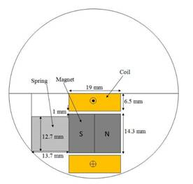
Finally, our goal is to design an energy harvest system that can harness the kinetic energy of the water to provide power for the electronic sensing and transmission systems. The design of the energy harvest system will facilitate the capture of energy from both impacts and random motion. It will eliminate the need for batteries, thus reducing maintenance costs and downtime. To date, design code has been developed to maximize energy harvest due to impact with pipe walls. This code has generated an initial design as shown in Figure 9.
Figure 9. Initial design of energy harvest system
Presently, a mechanical model is under development to fully characterize the rotational behavior of the device as it flows through the distribution system. This will enable the design code to maximize the energy harvest due to impact and random motion. The mechanical model of the device is nearly complete. Once this is complete, a final energy harvest system will be designed and its usefulness in replacing the battery evaluated. If there is significant promise that the energy harvest system will provide sufficient energy, it will be constructed and integrated into the sensor system.
For wireless mobile sensor networking, future work will center on two main issues: establishing a consistent RF link between the base station and mobile sensor and developing a data-logging algorithm on a control PC. Currently, work is underway to tune the RF operation of the mobile sensor and network base station in software, to permit consistent and valid data transmission. This is being done through TI’s debugging software in combination with spectrum analysis. A data-logging algorithm will be developed on a Windows PC to receive data from the network base station and store it in a spreadsheet for ease of storage and monitoring.
Journal Articles:
No journal articles submitted with this report: View all 15 publications for this projectProgress and Final Reports:
Original AbstractThe perspectives, information and conclusions conveyed in research project abstracts, progress reports, final reports, journal abstracts and journal publications convey the viewpoints of the principal investigator and may not represent the views and policies of ORD and EPA. Conclusions drawn by the principal investigators have not been reviewed by the Agency.