U.S. flag

An official website of the United States government

Here’s how you know

Dot gov

Official websites use .gov
A .gov website belongs to an official government organization in the United States.

HTTPS

Secure .gov websites use HTTPS
A lock (LockA locked padlock) or https:// means you have safely connected to the .gov website. Share sensitive information only on official, secure websites.

  • Environmental Topics
  • Laws & Regulations
  • Report a Violation
  • About EPA
Contact Us

Grantee Research Project Results

2013 Progress Report: Development of Mobile Self-Powered Sensors for Potable Water Distribution

EPA Grant Number: R834868
Title: Development of Mobile Self-Powered Sensors for Potable Water Distribution
Investigators: Banks, M. Katherine , Brovont, Aaron D , Salim, Amani , Porterfield, Marshall , Wu, Ruoxi , Pekarek, Steve , Jefferson, Travis
Institution: Purdue University
EPA Project Officer: Page, Angela
Project Period: January 1, 2011 through December 31, 2013 (Extended to December 31, 2014)
Project Period Covered by this Report: December 1, 2012 through January 2,2014
Project Amount: $599,997
RFA: Advancing Public Health Protection through Water Infrastructure Sustainability (2009) RFA Text |  Recipients Lists
Research Category: Drinking Water , Water

Objective:

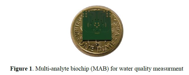
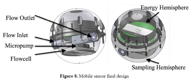
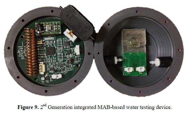
In this year’s effort, a second generation mobile sensor system is being designed and fabricated for water quality monitoring in a potable water distribution system. The research being conducted is focused on the areas of (1) sensor research and device fabrication, (2) packaging design and fabrication, (3) integration with electronic components, and (4) application testing of water quality sensors.

Progress Summary:

Sensor research and device fabrication
 
A multi-analyte biochip (MAB) system has been designed that consists of multiple ion-selective electrodes that are microfabricated on a silicon substrate. Potentiometric measurements in the millivolt range are recorded. The sensor is calibrated based upon laboratory experiment, and the concentrations of target analytes are determined from calibration curves taken for a respective sensor. To date, ion-selective electrodes have been made that are selective for H+, NH4+, Ca2+, Cl-, and CO32- ions, which are the key ions for pH, water hardness, and disinfectant. Over this past year, lifetime tests of the sensor were performed where calibration slopes for H+ were recorded over extended periods of time (10 days). A MAB is shown in Figure 1.
 
 
MAB design: The MAB design consists of six ion-selective-electrodes (ISEs) (Φ = 240 μm). All six of these electrodes are working electrodes (WEs) for potentiometric sensing, with three working electrodes (WEs) sharing one Ag/AgCl reference electrode (REs) (Φ = 480 μm). The biochip also houses three WEs each having its associated pseudo-reference electrode for amperometric sensing. All WEs and REs are located within a microfluidic chamber 6 mm in diameter. The overall biochip dimension is 10 x 11 mm.
 
MAB fabrication: Fabrication of the first generation MAB, which was intially considered in the previous year’s efforts but also continued this year, started with a silicon oxide wafer that is patterned with Ti/Pt electrodes of 30/150 nm respectively via lift off. Next, electrodes areas were passivated with oxide, exposing only the area of active WEs. Then, the conductive polymer poly(3,4-ethylenedioxythiophene)-poly-(styrenesulfonate) (PEDOT:PSS) was deposited via cyclic voltammetry at a scan rate of 20 mV/sec on the active WEs [1], followed by deposition of the ion-selective membrane (ISM) selective for specific analyte of interest via spin-coating at 1500 rpm. The ISM was dried in a desiccator overnight to remove unwanted solvents. A Ag/AgCl ink is deposited on reference electrode areas. Finally, the MAB was conditioned in ISM conditioning solution [3,4] that helps establish a stable potential at the ISM interfaces.

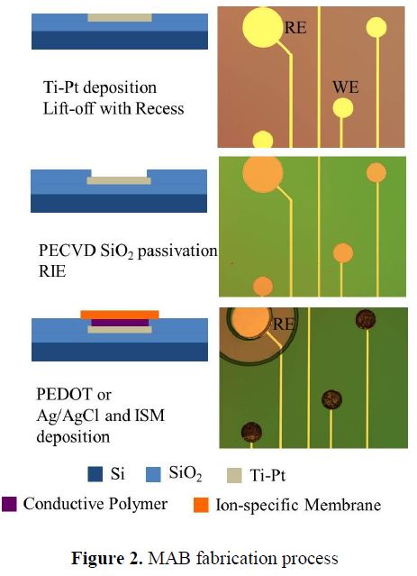
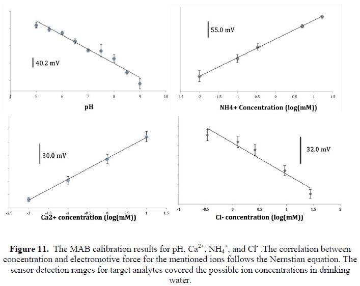
In the second generation MAB, the fabrication process was further refined by replacing the PEDOT:PSS WEs with Ag/AgCl and depositing a thinner ISM (e.g., drop-coating VS spin-coating) on the WEs. This is to ensure a faster response time (e.g., 5 min vs 1 min) and simplified the fabrication process (e.g., no electrochemical deposition of PEDOT:PSS is required). Additionally, a UV curable epoxy (Su8) was fabricated on the MAB to hold the O-ring in place to prevent leakage. Furthermore, the Ag/AgCl layer on the RE was deposited via chloriding bathing process in 4% sodium hypochlorite rather than using a Ag/AgCl ink. This is done by depositing an extra layer of Ag on top of the Pt of the working and reference electrodes. The detailed fabrication process is shown in Figure 2 for both the first and second generations.

ISM Materials: All reagents and chemicals were of analytical grade, were obtained from Sigma Aldrich (St. Louis, MO, USA), and were used without further purification, including, hydrogen ionophore I (H+ I), tridodecylmethylammonium chloride (tDMACl), potassium tetrakis(4-chlorophenyl)borate (KTCPB), high-molecular-weight polyvinyl chloride (PVC), bis (2-ethylhexyl) sebacate (DOS), polyurethane spheres (PU), cyclohexanone (selectophore grade) (CHX), 3,4-ethylenedioxythiophene (EDOT) monomer, and sodium polystyrene sulfonate (NaPSS).
 
ISM preparation: The quantities of the various membrane components of the ISM are based on the desired percentage for each and were calculated for a total weight of 500 mg. For the HISE membrane [2,3], PU [9.9 wt %] was dissolved in CHX [10% wt/vol]. Once the PU spheres were dissolved, PVC [23.1 wt %], KTCPB [0.5 wt %], DOS [65.5 wt %], and H+ I [1 wt %] were added to the PU/CHX mixture. PU was used in conjunction with PVC to increase the mechanical stability and adhesion of the ISM to the biochip surface [4,5]. All ISM solutions were left under constant stirring overnight to ensure proper mixing of membrane components. The recipe of all ISMs are shown in Table 1.
 
 
Packaging design and fabrication
 
The second generation mobile sensor is a 2.76 inch–diameter spherical shell containing a multi-analyte biochip, microfluidics, an electronic control system, and energy harvest system. The mobile sensor size is chosen for operation and movement in a water distribution pipe with a minimum diameter of 4 inches. Most water distribution pipes range in size from 4-inch to 36-inch nominal diameters.
 
The mobile sensor consists of two hemispheres as shown in Figure 3: the sampling hemisphere and the energy/electronics hemisphere. Each hemisphere is designed to segregate the internal components by function and secure them in place. The packaging is waterproof to protect vulnerable equipment from the outside environment, and the two hemispheres are sealed together with a Viton gasket.


The second generation sensor packaging was designed using commercially available CAD software (SolidWorks 2013 x64 Edition). Both hemispheres have a flat surface to facilitate the placement of their respective components. A 3D-printed prototype was constructed to confirm the feasibility of this design, shown in Figure 4. The final machined PVC shell is shown in Figure 5.


The sampling hemisphere consists of a flow cell chamber housing the MAB, which is a replaceable cartridge, and microfluidic components. The flow cell is connected via microtubing to an MP6 micropump (pumping rate of 160 μL per minute at a power of 200 mW). The micropump furnishes a water sample from the environment to the MAB. The MAB contact pads are wire-bonded to a printed circuit board (PCB) that is connected to the electronic control system in the opposite hemisphere via jumper cables. The flowcell chamber housing the MAB is constructed of clear acrylic material so that it will not interact with the chemicals in the water sample. The sensing chip is placed inside the flow cell with a gasket, where all working and reference electrodes are immersed in the sampled liquid. The flowcell cartridge with the MAB is relatively simple to remove from the package for calibration or replacement. The MAB, micropump, and flow cell cartridge are shown in Figure 6.
 
 
The flowcell chamber, modeled in Figure 7 (left), is custom built by laser cutting and joining acrylic pieces with pressure-sensitive adhesive (PSA). The advantage of this design is the reduced size and convenience of calibration with the simplified signal cable connector. Samples are conducted into and out of the device through ports and tubing connected with rivet nuts, shown in Figure 7 (right). The dimension and size of the tubing and rivet nuts are chosen to fit the shape and thickness of the sensor package.
 
 
The energy/electronics hemisphere consists of an electronic control system PCB and an air-core tubular permanent-magnet generator dubbed the energy harvest system. The function and design of these systems are described in greater detail in the next section.
 
 
The integrated device is shown in Figure 8 without the energy harvest system. In the final assembly, the flowcell cartridge and energy harvest system will be glued in place while the electronic control system PCB will be secured with screws. All remaining components will be affixed with glue or pressure-sensitive adhesive (PSA).
 
Integration with electronic components
 
The electronic control system has been designed to coordinate all device activity, read measurements from the MAB, and transmit data to remote base stations with the lowest possible energy consumption. A Texas Instruments (TI) CC430 microcontroller with integrated RF transceiver is the core around which the whole system is built. Its suite of peripheral devices, ultra-low power consumption, and minute footprint make it an ideal choice for the MAB-based water sensing application. In the past year, software has been developed for this platform to execute all necessary data acquisition, logging, and transmission functions. New in the second generation, energy harvest and battery protection systems have been designed for the incorporation of a rechargeable battery cell, which will reduce maintenance requirements and extend the device’s lifetime. A printed circuit board integrating all of the electronic control system components and the energy source has been designed, constructed, and tested. Details of this work are provided in subsequent sections. The complete integrated sensor is shown seated within the device shell in Figure 9. Tubing and jumper cables are omitted for clarity.
 
 
For wireless mobile sensor networking, a network base station has been designed to receive data from the mobile sensors and relay the data back to a control network or PC for monitoring and data logging. A base station prototype has been designed and constructed as shown in Figure 10. In the past year, wireless communication between the base station and mobile sensors has been achieved, and a graphical user interface has been developed for viewing and logging data on a local PC. Details are provided in subsequent sections.
 
 
Results to Date
 
MAB Sensor
 
The sensor operates based on the potentiometric electrochemical principle. The MAB shown in Figure 1 reacts with an analyte of interest and outputs an electrical signal that is proportional to the concentration of the analyte. An analyte that comes in contact with the sensor first passes through an ion-selective membrane (ISM) that is selective for the analyte of interest. The Nernst equation (Eqn. 1) defines the concentration of analyte for both sides (a1 and a2) of the ISM at equilibrium; the potential difference is translated into a voltage value (E). A plot of measured potential vs. analyte concentration is linear if the ISM is perfectly selective for the analyte of interest. For analytes of divalent and monovalent ions, the theoretical Nernstian slope is 59.2 and 29.6 mV/decade respectively.
 
 
In (1) R = universal gas constant, T = absolute temperature in K, z = charge of the analyte, and F = Faraday constant.
 
Sensor calibration: To date, ion-selective electrodes for the MAB have been made for H+, NH4+, Ca2+, Cl-, and CO32- ions, which are the key ions for pH, water hardness, anddisinfectant. Representative calibration slopes are shown in Figure 11. All calibration slopes are Nernstian, meaning the sensor is able to detect concentration of selected analytes.
 
 
The lifetime of the MAB sensor has been tested for the pH ion-selective electrode. After a MAB was conditioned, continuous introduction of samples of pH 6.3-8.3 was repeated from the first day. The drifted slope (voltage signal change detected over 1 unit of pH change) data is shown in Figure 12. Significant signal drift was not found until the eleventh day of testing. From this experiment, it is expected that an MAB sensor is reliable for at least 10 days after conditioning and calibration.
 
 
Table 2 compares the mobile sensor developed in this project to five models of EPA approved pH/ion sensor for water quality monitoring [10]. These water sensors used in field tests are ion-selective-glass based probe sensor. They need a bulky battery and several fragile glass probes for analyte detection. A mobile sensor has notable advantages of lightweight and package miniaturization, which are essential for its mobility when traveling in a water distribution system. In addition, the pH sensitivity and detection limit of this mobile sensor are sufficient for the drinking water sample monitoring.
 
 
As mentioned previously, mobile sensor electronic control system and network base station prototypes have been designed and constructed. The main design considerations for both prototypes are presented in greater detail in the following paragraphs.
 
The electronic control system on the mobile sensor is divided into three subsystems in the second generation design: digital, analog, and power. The digital subsystem consists of the CC430 microcontroller with integrated wireless transceiver, an external memory module, and the pump controller. The analog subsystem comprises an INA333 instrumentation amplifier to interface with the MAB sensor and a voltage reference for compatibility with the digital subsystem. The power subsystem, which is a key addition in the second generation design, is itself divided into three distinct systems: energy harvest, battery charging and protection, and voltage regulation. The digital, analog, and power subsystems are described in detail in the following sections.
 
Electronic Control System – Digital Subsystem
 
The digital subsystem has two main objectives, data acquisition and wireless communication, which are largely achieved through the native capabilities of the CC430 microcontroller. The other components of the digital subsystem, the external memory module and the pump controller, expand these capabilities to handle the specific needs of the mobile sensor application. The following paragraphs describe the theory of operation for data acquisition and communication between the mobile sensor and network base stations.
 
The Real-Time Clock on the CC430 coordinates all of the activities for data acquisition. The sampling rate is user-specified and is presently configured for 2-minute intervals. At the beginning of each data acquisition cycle, the pump is enabled and runs for a user-designated time period (presently 30 seconds). The pump turn-on/off is controlled by another of the CC430’s timer peripherals. The remainder of the sampling interval is a hold period to allow the MAB voltage to stabilize. At the conclusion of the cycle, the MAB terminal voltage is measured via the on-chip analog-digital converter (ADC) and stored locally along with a timestamp. Each sample requires seven bytes of memory, which is allocated dynamically at the time of sampling. The storage of the data sample completes the acquisition process, and the sampling cycle begins anew. As noted previously, the sampling rate and all timing intervals can be adjusted in software to meet the required settling times for the various MAB sensor architectures.
 
Once water quality data has been acquired on a mobile sensor, it must be transferred to a base station for monitoring and analysis. This is accomplished wirelessly by transmitting and receiving a sequence of control packets followed by a data payload and a checksum to ensure a valid transmission. In this application, a data “packet” comprises the seven bytes required for each sample, two for the voltage reading, three for the timestamp, and one each for a packet type identifier and a checksum for data handling purposes. The operational characteristics of the base station and the mobile sensor differ significantly; the mobile sensor is designed to transmit data payloads while the base station receives them. In short, the transmission scheme is a sequential relay of control packets: ready signal, device identification signal, data ready signal, data payload, checksum.
 
Data transfer from a mobile sensor to a base station is controlled by a ping timer on the base station, which is currently set in software for a two second period. On each ping, the first step in data transmission is attempted, a process known as handshaking. To begin the handshaking process, the base station broadcasts a ready signal, which indicates that it is ready to accept data. The mobile sensor is silent until this signal is detected. Upon detection, the sensor sends back a signal which uniquely identifies itself to the base station. The identification of each mobile device allows for a base station to communicate securely with a single mobile sensor regardless of the number of sensors within range. Once the base station selects a particular mobile sensor, a packet is sent back granting permission to that device to send data packets, completing the handshaking process. The sensor responds by sequentially transmitting and deleting each stored sample. It is noted that each data packet is validated by the base station, which notifies the sensor of a successful transmission before the data is deleted there. Data transmission continues with a single device until the samples are all transmitted successfully or an invalid packet is encountered. The ping timer is disabled during this handshaking process to allow for the possibility that an entire ping interval might transpire during a single transmission, although current operation appears to be much more rapid than the two-second interval. Once the data transmission terminates, the ping timer is re-enabled and the process begins anew.
 
Within this year, the data acquisition system and wireless communication designs highlighted in the previous paragraphs have been successfully designed and tested.
 
In addition, a new feature in the second generation design is the inclusion of an external memory module to lift the memory constraint set by minimal on-chip CC430 SRAM. This enables one to store data in the event that sensor-base communication is not possible or is only possible at long time intervals. To this end, a 64 kilobit (8192 bytes) FRAM chip has been added that will provide storage space for 1170 full seven-byte samples. The FRAM chip is controlled with an SPI communication bus, which is an included peripheral on the CC430 package.
 
Electronic Control System – Analog Subsystem
 
The analog subsystem provides the necessary signal conditioning to interface the MAB with the digital subsystem. The design objective for this interface is to maximize the resolution of the MAB output while satisfying the input requirements for the ADC, which is complicated by the unusual electrical characteristics of the MAB. The MAB has a very large output impedance, which makes the choice of amplifier critical (and challenging). Texas Instruments’ INA333 instrumentation amplifier was selected for this purpose due to its very high input impedance, low power consumption, rail-to-rail operating range, and small footprint. Together with the LPV511 op-amp employed as a voltage reference, the INA333 amplifies and offsets the floating, differential output voltage of the MAB. In the first hardware revision, three amplifier designs were constructed and tested. The basic functionality of the three designs was verified, and one design was selected for its simplicity and superior noise immunity. Additionally, it was determined that to achieve the design objective of maximum output resolution, the gain of the amplifier must be calibrated for the particular MAB sensor in use. This is achieved in the 2nd generation design through the inclusion of a potentiometer, which permits the INA333 a variable gain.
 
Electronic Control System – Power Subsystem
 
As outlined earlier, the power subsystem has three internal systems: energy harvest, battery charging and protection, and voltage regulation. The first of these is the energy harvest system, which is responsible for converting the kinetic energy of impacts and random motion into electrical energy. This system was designed in two stages. The first stage was a multi-objective optimization study with the goal of maximizing energy harvested per impact while minimizing the overall device radius. The curve which describes the best case relationship between energy harvest capabilities and size for the device is shown in Figure 13.
 
 
The intent of this study was to explore the feasibility of using the energy harvest system as the sole energy source. It was found in comparing the power needed for regular sampling with the expected harvesting capabilities for the desired device radius, that the energy harvest system should instead be a supplementary source responsible for recharging the primary energy source (i.e., a battery). It is expected that the inclusion of the energy harvest system will extend the device’s lifetime and reduce maintenance requirements. The second design stage was a single objective optimization study to maximize energy harvest subject to the actual shell dimensions and spatial constraints of the second generation packaging. The final design is shown in Figure 14. This system is currently being constructed for testing and validation.
 
 
The second section of the power subsystem is the battery charging and protection circuitry. The objectives of this system are to regulate the capacitor voltage on the output of the energy harvest system and to charge the battery while preventing over-charging or over-discharging the battery. The battery for this system was selected to be a single-cell, 240 mAh, Lithium-ion-polymer battery, which has a nominal 3.7 V open-circuit voltage. The constraints for this cell are a maximum charge rate of 1 C, a maximum discharge rate of 0.5 C, and upper and lower voltage bounds of 4.2 V and 2.7 V, respectively. In this system, a comparator monitors the voltage on the output capacitor of the energy harvest system. When this voltage rises above a given threshold (5.7 V) the buck converter operates to move charge from the capacitor to the battery. Another set of comparators monitor the battery voltage to prevent charging when the battery voltage is too high and to prevent discharging when the battery voltage is too low by shutting down the voltage regulator and all downstream components. It is noted here that the FRAM chip in the digital subsystem is non-volatile so that data will not be lost in the event of a low-voltage shutdown.
 
The third section of the power subsystem is the voltage regulator. This section consists mainly of Texas Instruments’ TPS63031 fixed-output 3.3V Buck-Boost converter chosen for its high efficiency, small footprint, and shutdown feature. A SPDT sliding switch toggles the shutdown pin of the converter between control by the battery protection circuitry and an OFF state.
 
Base Station to PC Data Transfer
 
The network base station has two main objectives: wireless communication with the mobile sensors and the relaying of data to a network PC or other external controller. As stated for the mobile sensors, wireless communication is handled natively on the CC430 microcontroller. The main challenge to wireless communication will be to determine the effective distance over which the mobile sensors and base stations will be able to consistently communicate due to water, metals, and other unknown conductive media obstructing the path of communication. This challenge will be addressed in the next stage of testing. The main design consideration for the base station was the interface with a PC or other external controller. To facilitate this interface, a circuit was selected to incorporate an FT232R USB to UART converter, which will allow communication with the base station through a standard USB connection. Permanent data logging may then be handled by a network PC, enabling a simple interface for monitoring and analyzing data. To this end, a graphical user interface (GUI) has been developed to receive and log data on a PC attached locally to a base station. A screenshot of the GUI is shown in Figure 15. This GUI provides a simple means to display the data for viewing or to store the data in a column, tab-delimited text format. Once stored, the data may be imported into a spreadsheet application for further analysis or manipulation.


Future Activities:

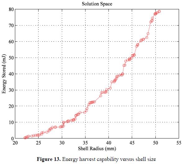
It is anticipated that in the final year, there are three avenues to pursue. First, to establish the energy harvest unit for the sensing system, we had developed relatively sophisticated models of the sensor movement. These will be validated so that the next generation of water sensor designers can have confidence in the energy per volume predicted in this research. This will entail adding an inertial measurement unit and the accompanying control software to the existing sensing system to measure movement. Second, in the initial efforts, we have been evaluating the possibility of adding leak detection to the suite of sensing options. We have purchased a hydrophone and data acquisition system and set up a testbed to perform acoustic noise studies. To date, we have not come to a conclusion about the practical implementation of such a sensor. Additional leak detection studies will be performed to come to some conclusion about whether a mobile sensor can be used in such an application. Finally, we would like to predict the expected transmission distance of the wireless sensors in a variety of pipe materials (plastic, metal), to enable the design of stationary antennas and the power required for the transmission.

References:

  1. D. S. Sakong, M. J. Cha, J. H. Shin, G. S. Cha, M. S. Ryu, R. W. Hower and R. B. Brown, Sensors and Actuators B-Chemical, 1996, 32, 161-166.
  2. D. Liu, M. E. Meyerhoff, H. D. Goldberg and R. B. Brown, Analytica Chimica Acta, 1993, 274, 37-46.
  3. N. H. Kwon, M. S. Won, D. S. Park and Y. B. Shim, Electroanalysis, 2005, 17, 641-647.
  4. S. Anastasova-Ivanova, U. Mattinen, A. Radu, J. Bobacka, A. Lewenstam, J. Migdalski, M. Danielewskic and D. Diamond, Sensors and Actuators B-Chemical, 2010, 146, 199-205.
  5. A. Bratov, N. Abramova, C. Dom ngue , A. Baldi, Ion-selective field effect transistor (ISFET)-based calcium ion sensor with photocured polyurethane membrane suitable for ionised calcium determination in milk, Analytica Chimica Acta 408 (2000) 57-64.
  6. M.S. Ghauri, J.D.R. Thomas, Evaluation of an ammonium ionophore for use in poly(vinyl chloride) membrane ion-selective electrodes: solvent mediator effects, Analyst 119 (1994) 2323-2326.
  7. M. Maj-Zurawska, M. Rouilly, W.E. Morf, W. Simon, Determination of magnesium and calcium in water with ion-selective electrodes, Analytica Chimica Acta 218 (1989) 47-59.
  8. M. Otto, J.D.R. Thomas, Model studies on multiple channel analysis of free magnesium, calcium, sodium, and potassium at physiological concentration levels with ion-selective electrodes, Analytical Chemistry 57 (1985) 2647-2651.
  9. M. Rothmaier, W. Simon, Chloride-selective electrodes based on mercury organic compounds as neutral carriers, Analytica Chimica Acta 271 (1993) 135-141.
  10. EPA, “Distribution System Water Quality Monitoring: Sensor Technology Evaluation Methodology and Results: A Guide for Sensor Manufacturers andWater Utilities,” 2009, EPA/600/R-09/076.
  11. GLI International, Inc., Operating Instrustion Manual of Hach/GLIModel P53 pH/ORP Analyzer, 2001, Rev. 7-1201
  12. YSI. Inc., 6-Series Multiparameter Water Quality Sondes User Manual, 2011. 11, Rev. H.
  13. Hach Company, Hydrolab DS5X, DS5, and MS5 Water Quality Multiprobes User Manual, 2006. 02, Edition 3.
  14. In-Situ Inc., Multi-Parameter TROLL 9000, WQP-100 Operator’s Manual, 2005, rev. 010 09/05


Journal Articles on this Report : 2 Displayed | Download in RIS Format

Publications Views
Other project views: All 15 publications 3 publications in selected types All 3 journal articles
Publications
Type Citation Project Document Sources
Journal Article Howard RA, Xiao Y, Pekarek SD. Modeling and design of air-core tubular linear electric drives. IEEE Transactions of Energy Conversion 2013;28(4):793-804. R834868 (2013)
R834868 (Final)
  • Abstract: IEEE-Abstract
    Exit
  • Journal Article Wan Salim WWA, Zeitchek MA, Hermann AC, Ricco AJ, Tan M, Selch F, Fleming E, Bebout BM, Bader MM, Ul Haque A, Porterfield DM. Multi-analyte biochip (MAB) based on all-solid-state ion-selective electrodes (ASSISE) for physiological research, Journal of Visualized experiments: JoVE 2013;74:50020. R834868 (2013)
    R834868 (Final)
  • Full-text from PubMed
  • Abstract from PubMed
  • Associated PubMed link
  • Abstract: JoVE-Abstract and Summary Video
    Exit
  • Supplemental Keywords:

    Contamination, drinking water, sensors, water distribution system, potable water distribution, security of drinking water system

    Progress and Final Reports:

    Original Abstract
  • 2011 Progress Report
  • 2012 Progress Report
  • Final Report
  • Top of Page

    The perspectives, information and conclusions conveyed in research project abstracts, progress reports, final reports, journal abstracts and journal publications convey the viewpoints of the principal investigator and may not represent the views and policies of ORD and EPA. Conclusions drawn by the principal investigators have not been reviewed by the Agency.

    Project Research Results

    • Final Report
    • 2012 Progress Report
    • 2011 Progress Report
    • Original Abstract
    15 publications for this project
    3 journal articles for this project

    Site Navigation

    • Grantee Research Project Results Home
    • Grantee Research Project Results Basic Search
    • Grantee Research Project Results Advanced Search
    • Grantee Research Project Results Fielded Search
    • Publication search
    • EPA Regional Search

    Related Information

    • Search Help
    • About our data collection
    • Research Grants
    • P3: Student Design Competition
    • Research Fellowships
    • Small Business Innovation Research (SBIR)
    Contact Us to ask a question, provide feedback, or report a problem.
    Last updated April 28, 2023
    United States Environmental Protection Agency

    Discover.

    • Accessibility
    • Budget & Performance
    • Contracting
    • EPA www Web Snapshot
    • Grants
    • No FEAR Act Data
    • Plain Writing
    • Privacy
    • Privacy and Security Notice

    Connect.

    • Data.gov
    • Inspector General
    • Jobs
    • Newsroom
    • Open Government
    • Regulations.gov
    • Subscribe
    • USA.gov
    • White House

    Ask.

    • Contact EPA
    • EPA Disclaimers
    • Hotlines
    • FOIA Requests
    • Frequent Questions

    Follow.