
Grantee Research Project Results
Final Report: Multifunctional Reactive Electrochemical Membrane (REM) Filtration forPFOA/PFOS Removal
EPA Grant Number: SU839452Title: Multifunctional Reactive Electrochemical Membrane (REM) Filtration forPFOA/PFOS Removal
Investigators: Zhang, Wen , Hua, Likun , Ma, Qingquan
Institution: New Jersey Institute of Technology
EPA Project Officer: Page, Angela
Phase: I
Project Period: December 1, 2018 through November 30, 2019
Project Amount: $15,000
RFA: P3 Awards: A National Student Design Competition Focusing on People, Prosperity and the Planet (2018) RFA Text | Recipients Lists
Research Category: P3 Awards , P3 Challenge Area - Safe and Sustainable Water Resources
Objective:
In this EPA P3 phase I project, we aimed to incorporate REM synthesis, characterization, and electro-reactive filtration experiments to determine the efficiency of PFOA/PFOS degradation and removal via REM filtration systems. The key research objectives include: (1) evaluate anodic oxidation of PFOA/PFOS on REM filtration; (2) Explore degradation mechanisms and degradation by products; (3) Analyze degradation byproducts; (4) Assess membrane fouling on REM and fouling mitigation measures.
Objective 1. Evaluation of the performance of REM for the removal of PFOA and PFOS.
Task 1.1: Preparation of monolithic Ti4O7 membranes. Our cylindrical REM filtration unit as shown in Fig. 1 has been fabricated to quantify the permeate flux and pollutant rejection over time. Monolithic Ti4O7 membranes were synthesized by a thermal reduction method in our laboratory.
Task 1.2: Characterization of REM properties. To delineate changes to REMs after use as well as physical and chemical interactions between pollutants and REMs, their physical, chemical, and electrical properties were characterized before and after filtration and with different backwash conditions. In addition, characterization of REMs after repeated use also helps to elucidate material leaching, changes in electrochemical activity, and REM dimensional stability.
Task 1.3: Selection and analytical methods of PFASs. We spiked two model PFASs identified in the USEPA UCMR-3: perfluorooctanesulfonic acid (PFOS) and perfluorooctanoic acid (PFOA). Their spiked concentrations were 10 ppb up to 10 ppm. The concentrations of these selected compounds are measured based on EPA 537.1 method. Anions (fluoride and chloride), as well as perchlorate, are analyzed via ion chromatography using EPA Methods 300.0 and 314.2, respectively.
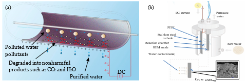
Fig. 1. (a) The schematics of electrochemical reactions in the membrane filtration process; (b) Our prototype of the electrochemically reactive filter device that has been developed in the phase I P3 project.
Task 1.4: Assessment of degradation kinetics and mechanisms of PFASs substances by REM. Degradation kinetics were tested by both batch reaction and continuous filtration. The batch reaction could be operated in a 500-ml beaker, where REM filter was placed into and charged at different electrode potentials (approximately 1.3 V-5 V) using a DC power supply (Proteck P6035, Tempe, AZ) corresponding to the current density between 1-10 mA∙cm-2 and for different times (10‒40 min). The filtrate was collected and the organic content in water is detected by a Shimadzu total organic carbon (TOC) analyzer (Nakagyo-ku, Kyoto, Japan) to examine the separation efficiency. Particularly, we evaluated the removal rates of PFASs from water (by monitoring TOC in permeate) under different DC currents or voltages, different filtration fluxes and organic matter loadings while filtration. Different DC currents or voltages are expected to induce different levels of anodic polarization and oxidation potential that in turn creates oxidative degradation, electrostatic repulsion or scouring against PFASs.
Objective 2. Assessment of stability and anti-fouling performance of REM in the treatment of PFAS water
At certain time intervals, backwashing is needed to remove foulant buildup on the surface of the REM membrane, especially for dead-end filtration, where organic pollutants may accumulate on membrane surface and lead to fouling with reduced performance of membrane filtration. However, the antifouling features against the PFASs substances are not yet known and deserve investigations for guiding the design and operations of REM system for practical applications.
Task 2.1: Evaluation of REM surface fouling. The hypothesis is that without DC polarization, REM may undergo high potential of fouling by PFASs (especially significant on dead-end mode). After repeated filtration tests with or without applying DC currents to REM anode, we examined the surface characteristics (e.g., morphology, conductivity or phase) of the REM by FTIR or Raman mapping to determine surface deposition of PFASs or their degradation products; furthermore, the permeate flux over time will be monitored to delineate the time-resolved kinetics of flux decline (e.g., lower than 60% of original clean water flux), which implies membrane fouling. Ideally, the observation is that under DC currents, permeate flux should decline less significantly over time compared to filtration without DC or with lower DC currents.
Task 2.2: Evaluation of antifouling and defouling operations on REM. Different combinations of membrane cleaning techniques have been applied: (1) hydraulic water backwash with/without applying DC currents of different levels (1-10 mA∙cm-2); (2) chemical cleaning using NaOH solution (pH 11) and H2SO4 (pH 3) solutions may be conducted for highly fouled membranes whose water flux cannot be recovered with hydraulic backwash and DC currents; (3) anode and cathode will be periodically switched to dissolve or repel membrane-adsorbed foulants. For these three backwash operations, the same TMP pressure (75 kPa) and the cleaning time (30 min - 1 hour) will be used.
Summary/Accomplishments (Outputs/Outcomes):
Major results. This phase I research verified the concept of electrochemical degradation of PFASs and also promote the design of novel reactive and anti-fouling REM filtration devices that are deployed on endpoint of water supply (e.g., tap water facet, water fountain, portable drinking machines and mobile drinking water treatment facilities). Moreover, the project research will help PI develop new teaching modules, laboratory manuals, interdisciplinary learning activities, and professional development activities targeted at a diverse student population from chemistry, biology, environmental and chemical engineering. For instance, the research tasks are well incorporated into the teaching activities in the undergraduate course-Introduction to Environmental Engineering (ENE262) in spring 2019. Students learnt about the micropollution issues in natural waters such as rivers and groundwater aquifers and then analyzed how water micropollution compromises potentially potable sources from being used as drinking water. Emphasis was made on the situation in the United States, where approximately two-thirds of the over 1,200 most serious hazardous waste sites in the nation are contaminated with trichloroethylene (TCE), a potentially carcinogenic compound. The lectures helped students understand the importance of developing and transforming physical filtration processes to chemically reactive systems that proactively react with water contaminants while filtration to improve removal efficiency of water pollutants at the endpoint drinking water supply to safeguard human health.
2.2. Preparation and Characterization of Ti4O7 REM.
Monolithic Ti4O7 membranes were synthesized by a thermal reduction method in our laboratory. Ceramic TiO2 membranes were purchased from Vector Corrosion Technologies Ltd. with variations in dimensions, such as (1) 250 mm long tubes with a 10 mm outer diameter and 6.0 mm inner diameter. and (2) 100 mm long tubes with a 27.7 mm outer diameter and 20.0 mm inner diameter. All TiO2 membranes have a pore size of 0.14 µm. Membranes were reduced at 1050 oC under H2 gas for 10 hours.
The total electrical resistance (R) was measured by Multi-meter (EXTECH INSTRUMENTS, MN26T) before and after the reductive thermal treatment. The conductivity reduced after the original TiO2 filter was thermally reduced to Ti4O7. The electrical resistivity changed from 4-6 Ω∙cm to 1.5-3.5 Ω∙cm, which agrees with previous studies.7
Surface zeta potential of REM in water was investigated by the Malvern DLS. The original TiO2 filter was more negative (-55 mV) than the thermally reduced REM (-30 mV), probably because the Ti4O7 REM has reduced surface oxygen atoms or functional groups after the thermal reduction.
FTIR analysis was used to verify the change of surface composition or functional groups. As shown in Fig. 2a, the green spectrum corresponds to TiO2 (rutile) while the red spectrum has a shift of the first peak at 721 cm−1due to TiO2 changed to Ti4O7 after the thermal treatment. The REM surface was imaged previously by Dr. Brian P. Chaplin’s group with Hitachi S-4800 cold field emission scanning electron microscopy (SEM).8, 9 XRD analysis was conducted with Siemens D5000 X-ray diffractometer.2 The SEM image in Fig. 2b shows an inhomogeneous and porous structure of the REM. The XRD characteristic peaks for Ti4O7 and Ti6O11 are located at 2 theta angles of 20.78° and 22.84°, respectively.10 The two peaks in Fig. 2c indicates that the REM consists primarily of Ti4O7 and Ti6O11.2 Peaks characteristic of TiO2 were not present, which indicates a full conversion from TiO2 to the Magnéli phase was accomplished.2
The overall porosity (Pr) was determined by a gravimetric method.11 The membrane mean pore radius (rm) was calculated by the Guerout–Elford–Ferry equation based on the pure water flux and porosity data.12, 13 The porosity for untreated and thermally treated REM remained almost unchanged at 14-15%. The mean pore size, however, was shown to reduce slightly from 524±32 nm to 408±7 nm for untreated and treated REM respectively, which agrees with previous studies.14
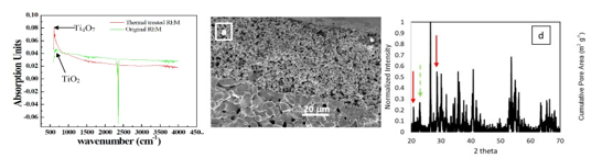
Fig. 2. (a) FTIR spectra of rutile TiO2 and Ti4O7. (b) Overall SEM image of the cross-section profile of REM. (c) XRD of REM with red (solid) and green (dash) arrows representing standard characteristic peaks of Ti4O7 and Ti6O11. Data cited from ref.2
2.3. Degradation kinetics and mechanisms of PFASs A recent study compared the degradation of PFOA and PFOS via electrooxidation by three common anodic materials, Ce-PbO2, boron-doped diamond, and the Ti4O7 REM anode, at a constant current density of 5 mA∙cm−2 in Fig. 3.1 The Ti4O7 ceramic anode shows a faster PFOA decay rate than the Ce-PbO2 and BDD electrodes, which also have been proven effective for PFOA degradation.15, 16 The change of PFOA concentration well fitted the pseudo-first-order model, based on which the half-life (t1/2) values were calculated as 34.65, 25.67, and 20.29 min for Ce-PbO2, BDD, and the porous Ti4O7 ceramic electrode, respectively. Although the anode potentials were much high than the decomposition voltage of PFOS (about 2.7 V vs. SHE),17 PFOS
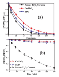
Fig. 3. Concentration change degradation was minor as shown in Fig. 3b, if any, on the BDD of 0.5mM PFOA (a) and (Ti/BDD, DiaChem®, Condias, Germany) and Ce-PbO2 0.1mM PFOS (b) during electrode used in this study, and after 3 h electrolysis, nearly no electrooxidation process by inorganic product, F− and SO42−, was detected in the bulk different anodes cited from1 solution. However, continuously rapid decay of PFOS on the porous Ti4O7 ceramic electrode was observed with a t1/2 of 52.62 min based on an estimate by pseudo-first-order kinetics. A recent study evidenced PFOS degradation over a Nb/BDD (DiaChem®, Condias, Germany) anode but at a very slow rate,18 while an earlier study reported PFOS decomposition over a Si/BDD electrode.17
To elucidate the possible mechanism of PFOA/PFOS degradation, intermediate products of PFOA/PFOS were analyzed which indicated that PFCAs with shorter chain involved from the degradation of PFOA. This is contrary to the few other degradation methods, such as photolysis and persulfate oxidation, by which PFOA tend to degrade stepwise by ripping off a CF2 unit each step. It thus takes eight steps to eventually turn the eight carbons in PFOA into CO2 and HF. The minimal production of intermediate products suggests predominant direct mineralization of PFOA molecules over the anode surface, consistent with what was reported elsewhere.1 This was made possible probably by the fact that Ti4O7 electrode allows for both direct electron transfer of PFOA and production of highly reactive ·OH at a rate of 2×10⁻⁹ mol cm−2 min−1 under an applied current density of 0.5 mA cm−2.19 Similar to PFOA mineralization process, PFOS and its degradation intermediates likely degrades via a combination of direct electron transfer and reaction ·OH. Firstly, the reaction was initiated by transferring an electron from the sulfate head group of PFOS to the anode, to form C8F17SO3· (Eq. 1). The C-S bond will then become extended and cleaved to form C8F17· and SO3 (Eq. 2).17 Subsequently, SO3 will transform to SO42− in aqueous solution, while the produced C8F17· reacts with ·OH to produce C8F17OH, and then reacts with another ·OH with a hydrogen atom abstracted to generates C8F17O· (Eq. 3), rather than decompose to C8F15OF and HF. C8F17O· can be easily cleaved to C7F15· and CO2 (Eq. 4). By repeating this CF2-unzipping cycle (C8F17· to C7F15·), the activated PFOS (C8F17SO3·) can completely mineralize to CO2 and HF over the porous Ti4O7 ceramic anode. All these processes can occur concurrently over Ti4O7 electrode surface because it is highly effective in both direct electron transfer and generating free ·OH.
| 𝐶𝐶8𝐹𝐹17SO3− →𝐶𝐶8𝐹𝐹17SO3 · +e− | (1) |
| 𝐶𝐶8𝐹𝐹17SO3 ·→𝐶𝐶8𝐹𝐹17⋯SO3 ·→𝐶𝐶8𝐹𝐹17 · +SO3 | (2) |
| 𝐶8𝐹𝐹17 · + · OH →𝐶𝐶8𝐹𝐹17OH+ · OH →𝐶𝐶8𝐹𝐹17OH⋯OH →𝐶𝐶8𝐹𝐹17𝑂𝑂 · +𝐻𝐻2𝑂𝑂C | (3) |
| 𝐶𝐶8𝐹𝐹17𝑂𝑂 ·→𝐶𝐶7𝐹𝐹15 · +COF2 | (4) |
| COF2+H2𝑂𝑂→ CO2 + 2HF | (5) |
| SO3+H2𝑂𝑂→ SO2−4 + 2𝐻𝐻+ | (6) |
The intermediates between PFOS and CO2 and HF were not found in the solution phase, while trace amounts of shorter chain PFCAs were detected during PFOA mineralization process. This difference may be attributed to that PFOS is more strongly adsorbed on the anode via electroassisted sorption, partly because of the higher charge density on the sulfate than the carboxyl group20 and the stronger acidity of PFOS. Therefore, nearly no degradation products were released to the bulk solution phase before their mineralization to F−, SO42− and CO2. In the case of PFOS decomposition by zero valent iron reduction under sub-critical water, no intermediates except F− were observed in the bulk solution phase as well.21 More research is needed to further clarify the degradation pathways of PFOS in electrochemical systems.
Conclusions:
2.4. Membrane fouling assessment
Currently, we are still working to obtain fouling assessment data in the treatment of PFASscontaining water. However, our prior work assessed the fouling and fouling mitigation of REM when filtering algal suspension, for which critical fluxes, filtration performances and fouling kinetics were systematically analyzed under different DC currents. The results indicate that critical flux could be increased when applying positive DC currents of greater than 2.5 mA·cm-2to the ceramic membrane compared to the critical flux without DC (6.3×10⁻⁵·m3·m-2·s-1). This means that the electrochemical reactions on REM under DC currents inhibited membrane fouling caused by the organic matters in algal suspension. Similarly, applying negative DC currents (e.g., -1.25~2.5 mA·cm-2) significantly mitigated membrane fouling and thus increased the critical flux (up to 14.6×10⁻⁵·m3·m-2·s-1). We established fouling kinetics model, which permits the calculation and prediction of foulant layer growth. This model could be utilized to analyze other organic fouling scenarios such as PFASs-related fouling processes.
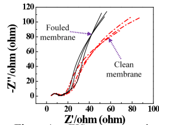
Fig. 4.EIS spectra in complete frequency range for clean and fouled REM.
Moreover, we also established the Electrochemical Impedance Spectrometry (EIS) method to measure the fouling occurences on REM. The interfacial impedance changes measured by EIS can sensitively indicate the foulant adsorption onto the REM surface.2For instance, the impedance data inFig. 4is presented graphically on a complex plane Z⁎(ω) known as a Nyquist plot, where -Zimgis plotted versus Zreal. The semicircle of Nyquist plot provides a dynamic changes of the foulant deposition layer on REM.22
2.5. Assessment of electrochemical degradation capability of REM for other different micropollutantsTi4O7REM was also tested for the degradation of1.0organic dye such as methylene blue (MB), rhodamine B0.8(RB) and orange II (OGII) in aqueous solution. Batch0.6reaction and filtration studies have been conducted for Filtration three different dyes to assess the removal capability of0.4w/o DC REM to remove in the aqueous phase. Moreover, the0.2REM as anode electrochemical oxidation of 1,4-dioxane with Ti4O7REM as cathode electrode was also investigated.Fig. 5shows the decline0 2 4 6 8 10 12 14 16of 1,4-dioxane concentration in continuous dead-endCurrent density (mA·cm-2)filtration with current density from 0 to 15 mA∙cm-2.
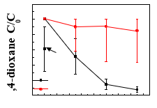
Fig. 5.The stable 1,4-dioxane concentration (C) in the permeate under REM served as anode and cathode.
When REM served as different current densities in continuous anode, as the current density increasing from 5 to 15 membrane filtration process. The results mA∙cm-2,there was appreciable decrease of 1,4-dioxane is expressed as the ratio of C/C0, where C0concentration up to 90%. Nevertheless, when making is the initial 1, 4-dioxane concentration REM as cathode, the 1,4-dioxane degradation were almost (49.52 ppm). The TMP was 75 kPa negligible, highlighting the key role of electrooxidation for pollutant degradation.
References:
1. Lin, H.; Niu, J.; Liang, S.; Wang, C.; Wang, Y.; Jin, F.; Luo, Q.; Huang, Q., Development of macroporous Magneli phase Ti4O7 ceramic materials: As an efficient anode for mineralization of poly-and perfluoroalkyl substances.Chemical Engineering Journal2018,354, 1058-1067.
2. Jing, Y.; Guo, L.; Chaplin, B. P., Electrochemical impedance spectroscopy study of membrane fouling and electrochemical regeneration at a sub-stoichiometric TiO 2 reactive electrochemical membrane.Journal of Membrane Science2016,510, 510-523.
3. Zaky, A. M.; Chaplin, B. P., Porous substoichiometric TiO2 anodes as reactive electrochemical membranes for water treatment.Environmental science & technology2013,47, 6554-6563.
4. Chaplin, B. P.; Duran, M.; Zaky, A. M.; Ding, K. InSubstoichiometricTitanium Dioxide Reactive Electrochemical Membranes for Water Treatment, Abstr. Pap. Am. Chem. S., AMER CHEMICAL SOC 1155 16TH ST, NW, WASHINGTON, DC 20036 USA: 2013.
5. Liu, H.; Vecitis, C. D., Reactive Transport Mechanism for Organic Oxidation During Electrochemical Filtration: Mass-Transfer, Physical Adsorption, and Electron-Transfer.J. Phys. Chem. C2011,116, 374-383. 6. Zaky, A. M.; Chaplin, B. P., Mechanism of p-substituted phenol oxidation at a Ti4O7 reactive electrochemical membrane.Environmental science & technology2014,48, 5857-5867.
7. Acha, C.; Monteverde, M.; Nunez-Regueiro, M.; Kuhn, A.; Franco, M. A., Electrical resistivity of the Ti4O7 Magneli phase under high pressure.The European Physical Journal B-Condensed Matter and Complex Systems2003,34, 421-428.
8. Zaky, A. M.; Chaplin, B. P., Porous Substoichiometric TiO2Anodes as Reactive Electrochemical Membranes for Water Treatment.Environ. Sci. Technol.2013,47, 6554-6563.
9. Zaky, A. M.; Chaplin, B. P., Mechanism of p-Substituted Phenol Oxidation at a Ti4O7 Reactive Electrochemical Membrane.Environ. Sci. Technol.2014,48, 5857-5867.
10. Walsh, F.; Wills, R., The continuing development of Magnéli phase titanium sub-oxides and Ebonex® electrodes.ElectrochimicaActa2010,55, 6342-6351.
11. Yu, S.; Zuo, X.; Bao, R.; Xu, X.; Wang, J.; Xu, J., Effect of SiO2 nanoparticle addition on the characteristics of a new organic–inorganic hybrid membrane.Polymer2009,50, 553-559.
12. Vatanpour, V.; Madaeni, S. S.; Rajabi, L.; Zinadini, S.; Derakhshan, A. A., Boehmite nanoparticles as a new nanofiller for preparation of antifouling mixed matrix membranes.Journal of Membrane Science2012,401–402, 132-143.
13. Zinadini, S.; Zinatizadeh, A. A.; Rahimi, M.; Vatanpour, V.; Zangeneh, H., Preparation of a novel antifouling mixed matrix PES membrane by embedding graphene oxide nanoplates.Journal of Membrane Science2014,453, 292-301.
14. Nayak, S.; Chaplin, B. P., Fabrication and characterization of porous, conductive, monolithic Ti4O7 electrodes.ElectrochimicaActa2018,263, 299-310.
15. Schaefer, C. E.; Andaya, C.; Burant, A.; Condee, C. W.; Urtiaga, A.; Strathmann, T. J.; Higgins, C. P., Electrochemical treatment of perfluorooctanoic acid and perfluorooctane sulfonate: Insights into mechanisms and application to groundwater treatment.Chemical Engineering Journal2017,317, 424-432. 16. Lin, H.; Niu, J.; Ding, S.; Zhang, L., Electrochemical degradation of perfluorooctanoic acid (PFOA) by Ti/SnO2–Sb, Ti/SnO2–Sb/PbO2 and Ti/SnO2–Sb/MnO2 anodes.Water research2012,46, 2281-2289.
17. Carter, K. E.; Farrell, J., Oxidative destruction of perfluorooctane sulfonate using boron-doped diamond film electrodes.Environmental science & technology2008,42, 6111-6115.
18. Trautmann, A.; Schell, H.; Schmidt, K.; Mangold, K.-M.; Tiehm, A., Electrochemical degradation of perfluoroalkyl and polyfluoroalkyl substances (PFASs) in groundwater.Water Science and Technology2015,71, 1569-1575.
19. Liang, S.; Lin, H.; Yan, X.; Huang, Q., Electro-oxidation of tetracycline by a Magnéli phase Ti4O7 porous anode: Kinetics, products, and toxicity.Chemical Engineering Journal2018,332, 628-636.
20. Moroi, Y.; Yano, H.; Shibata, O.; Yonemitsu, T., Determination of acidity constants of perfluoroalkanoic acids.Bulletin of the Chemical Society of Japan2001,74, 667-672.
21. Hori, H.; Nagaoka, Y.; Yamamoto, A.; Sano, T.; Yamashita, N.; Taniyasu, S.; Kutsuna, S.; Osaka, I.; Arakawa, R., Efficient decomposition of environmentally persistent perfluorooctanesulfonate and related fluorochemicals using zerovalent iron in subcritical water.Environmental science & technology2006,40, 1049-1054.
22. Sim, L.; Wang, Z.; Gu, J.; Coster, H.; Fane, A., Detection of reverse osmosis membrane fouling with silica, bovine serum albumin and their mixture using in-situ electrical impedance spectroscopy.Journal of membrane science2013,443, 45-53.
Journal Articles on this Report : 1 Displayed | Download in RIS Format
| Other project views: | All 5 publications | 1 publications in selected types | All 1 journal articles |
|---|
| Type | Citation | ||
|---|---|---|---|
|
|
Hua L, Cao H, Ma Q, Shi X, Zhang X, Zhang W. Microalgae filtration using electrochemically reactive ceramic membrane:filtration performances, fouling kinetics and foulant layer characteristics. Environmental Science & Technology 2020; 54(3):2012-2021. |
SU839452 (Final) |
Exit |
Supplemental Keywords:
PFASs removal, sustainable water treatment, membrane filtration, reactive membrane, POU treatment deviceRelevant Websites:
The perspectives, information and conclusions conveyed in research project abstracts, progress reports, final reports, journal abstracts and journal publications convey the viewpoints of the principal investigator and may not represent the views and policies of ORD and EPA. Conclusions drawn by the principal investigators have not been reviewed by the Agency.