
Grantee Research Project Results
Final Report: Passive Unitized Regenerative Fuel Cell (PUReFC) for Energy Storage in Off-grid Locations
EPA Grant Number: SU835288Title: Passive Unitized Regenerative Fuel Cell (PUReFC) for Energy Storage in Off-grid Locations
Investigators: Fabris, Drazen , Lele, Sandeep , Sizemore, Michael , Krishnan, Shoba
Institution: Santa Clara University
EPA Project Officer: Hahn, Intaek
Phase: II
Project Period: August 15, 2012 through August 14, 2014 (Extended to August 14, 2015)
Project Amount: $89,023
RFA: P3 Awards: A National Student Design Competition for Sustainability Focusing on People, Prosperity and the Planet - Phase 2 (2012) Recipients Lists
Research Category: Pollution Prevention/Sustainable Development , P3 Challenge Area - Air Quality , P3 Awards , Sustainable and Healthy Communities
Objective:
The goal of this project was research into fuel cell performance and mechanical and electrical design to develop a portable, autonomous, and unitized regenerative fuel cell capable of providing energy to meet demands in off-grid applications. When coupled with a photovoltaic cell, the system will manage energy supply and demand to ensure uninterrupted renewable power. The fuel cell innovation is the addition of capillary wicking structures for water supply and removal from the proton exchange membrane.
The first generation prototype design (Phase I 2011-2012) suffered measured performance decay during sustained operation as well as observed anode water flooding. Second generation prototype development focused on redesigning the overall system, improving the capillary wicking structure transport distance and the contact with the water storage structure, developing the manufacturing process for the integrated flow field plates and wicking structure, as well as refining the gas sealing system. The system will be re-evaluated on efficiency, output, power density, and price competitiveness during the extension period.
The findings of this report primarily focus on the design and fabrication of an improved prototype with passive water management. Based on analysis and observation of first generation prototype operation, the revised design/fabrication approach implements a shorter transport distance within the porous wicks as well as a two-stage gas sealing design. A new fabrication methodology was developed to to improve interfacial contact between porous domains and provide better control over porous polymer structure resolution.
Summary/Accomplishments (Outputs/Outcomes):
The goal of this phase of the project was to test the first generation design to determine performance characteristics, develop a second generation design to alleviate some of these problems, and if possible move to beta testing with a solar system. It was determined that the first generation design suffered from water flooding over intermediate times, five to ten minutes, due to an imbalance in the water transport rate (shown below in Figures 2 and 33 and Table 1). The second generation system was redesigned to reduce the wicking flow path and hence improve the water transport. To achieve this they system was redesigned and a manufacturing process was developed. Unfortunately the second generation testing showed problems with the MEA which we were unable to resolve at the close of the project. Performance of the first generation system and the manufacturing and design work for the second generation system were reported to the professional community via conference papers during this phase of the project.
During Phase I testing, initial short-term characterization of discharge and charge mode performance showed results close to the analytical predictions for short times. However, characterization of long-term performance showed a drop in current density consistent with water flooding. Phase II focused on the issues causing performance degradation. Water transport and partial pressure calculations were performed along with a preliminary analytical model for water transport within the wicks. The system was redesigned to reduce the water transport distance and the contact to the water storage structure. The fabrication method was developed and the new system has undergone some preliminary testing.
First Generation Prototype Additional Testing: As a means to determine aspects of design that required review, additional transient discharge testing was conducted for the first generation prototype. These data present general trends of long term performance stabilization at the expense of reduced power output, Figure 1. The current density curves in Figure 2 initially exhibit a stage of rapid current density rise as the membrane electrode assembly (MEA) re-hydrates.
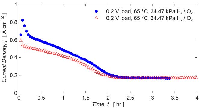 | 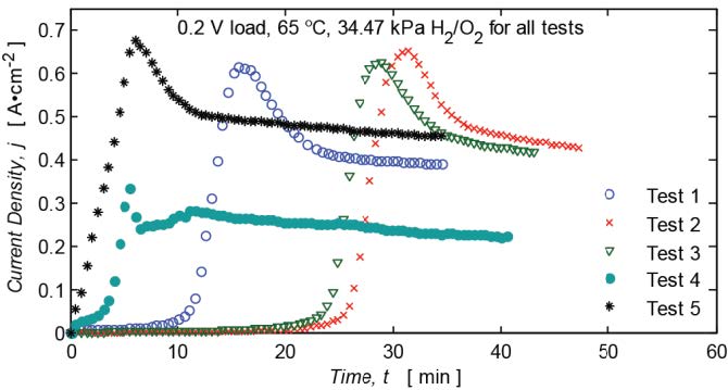 |
| Figure 1: First generation prototype transient discharge testing at 0.2V loading for two deparate experiments | Figure 2. First generation prototype transient discharge testing at 0.2V loading. After membrane hydration which occurred at variable times, current flow dropped by 20% and slowly degraded over time |
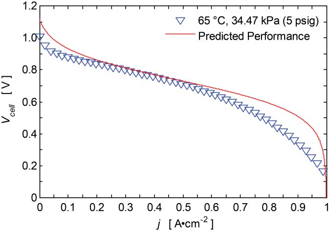
After experiments membrane hydration which occurred at variable times, current flow dropped by 20% and slowly degraded over time.This rise in current density is consistent with the relationship between MEA water uptake and proton conductivity[1]. It is hypothesized that the current density degradation that follows the initial current rise is associated with flooding of the cathode gas diffusion layer (GDL). The hydrophilic GDL saturates, which increases gas transport resistance—resulting in a reduced reaction rate. This fits well with measured discharge polarization curves in which GDL saturation causes additional concentration loss at higher current densities, Figure 3. The data indicate that water transport rates within the porous wicks were insufficient. Ideally, the passive management should prevent GDL/channel flooding while still leaving enough water at catalyst sites for oxygen reduction to continue. For sustained operation, balancing the rate of back-diffusion with the rate of electro-osmotic drag is critical. To identify equilibrium water partial pressure values that match back-diffusion to electro-osmotic drag, the water rate balance was calculated for various operating current densities. Low values of equilibrium partial pressure differentials (ΔPeq) presented in Table 1 are further indicators that insufficient water removal will result in back-diffusion overcoming electro-osmotic drag—leading to cell flooding.
Figure 3. First generation prototype discharge polarization curve (~10 min span).
| Current Density, j[A cm-2 | Equilibrium Water Partial Pressure Differential, ΔPeq [Pa] |
|---|---|
| 0.1 0.5 1.0 | ~400 |
Table 1. Selected calculation values for equilibrium water partial pressure differential across the MEA at 0% initial anode relative humidity.
Second Generation Design/Prototype: The radial design of the first generation prototype, with flow channels diverging from a central inlet port, resulted in a large range of wick transport lengths to reach the water storage structure (1.5-12 mm). In this layout, the pressure gradient through the wicks was largely driven by the pressure derived from the gas flow in the channels. During dead-ended operation (non-recirculating gas), flow within the channels is dictated by the reaction rate—resulting in very low flow rates and low or negative pressure gradients. In this case, water transport mostly stagnates in the longer wicks due to an insufficient driving pressure gradient.
Figure 4. Second generation PUReFC prototype assembly with WSS directly behind the FFPs.
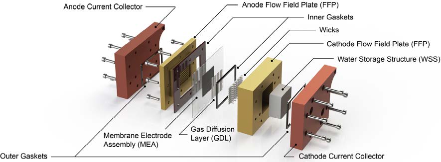
The second generation Passive Unitized Regenerative Fuel Cell (PUReFC) design primarily seeks to reduce the wicking transport distance to approximately 3 mm. The new design also ensures that all the wick transport lengths are uniform across the cell active area. The prototype has a 5 cm2 active area and 1 mm deep by 1.2 mm wide parallel gas channels, and contains both inlet and outlet ports for each reactant gas allow for operation either in a non-recirculating or a recirculating mode (a new feature). The inclusion of outlet ports should improve the purging and conditioning process. Double-sided machined components as well as a two-stage seal are incorporated into the design. In this arrangement, gaskets are used to seal against a metal surface with the MEA sandwiched in between. An inner gasket prevents oxygen leakage by sealing against the anode (H2) flow field plate (FFP), while an outer seal prevents hydrogen leakage by sealing against the cathode (O2) FFP. The two-stage design eliminates the need for perfect alignment of hydrogen and oxygen gaskets during assembly. For easier complete cell assembly, two sub-assemblies are used: an inner assembly including both FFPs, gaskets, gas diffusion layers (GDLs), and the MEA, assembled firs; an outer assembly consisting of copper current collector plates and additional gaskets.
The key feature of the design is the coupling of the porous polymer wicks within the cathode FFP to a porous Water Storage Structure (WSS) which acts as a storage reservoir for water generated from discharge operation, shown in Figures 8 and 9. The capillary pressure gradient across these two porous domains is designed to be the primary driver of water transport. The fabrication process of the porous wick structure was a novel development of this project. The wicks are fabricated from 2-hydroxyethylmethacrylate-co-ethylene dimethacrylate (HEMA-co-EDMA) using a UV lithographic method. A porous polyvinyl alcohol (PVA) sponge is used for the WSS. The WSS is housed in a cavity underneath the FFP channels. Short through-holes filled with HEMA-co-EDMA act as hydraulically conductive vias that connect the in-channel wicks and the WSS. Water produced at cathode catalyst sites moves downwards during discharge operation and upwards during charge operation. The new design also seeks to eliminate issues of poor interfacial contact by incorporating a large contact area between the porous polymer and WSS. This is a thin region of polymerization on the back side of the flow field plate (Figures 9 and 12b).
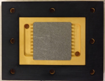 | 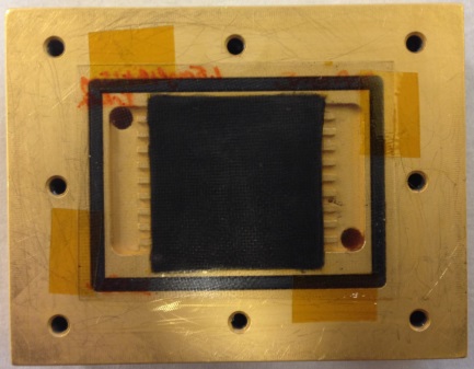 | 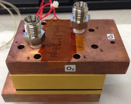 |
| Figure 5. Gold-coated titanium anode FFP. A sintered titanium GDL is installed above flow channels. An EPDM outer gasket seals H2, with the MEA sandwiched in between it and cathode FFP. | Figure 6. Gold-coated titanium cathode FFP. The MEA is installed above the sintered titanium GDL and inner EPDM gasket. The gasket seals O2, with the MEA sandwiched in between it and the anode FFP. | Figure 7. Fully assembled second generation PUReFC prototype. Copper current collector plates with inlet and outlet ports are shown at top and bottom. |
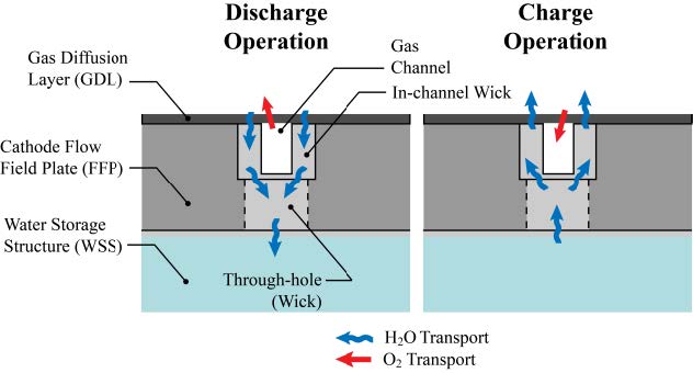 | 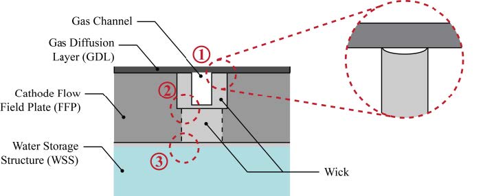 | |
| Figure 8. New passive water management operational schematic (cross section shown). The surface of the gas transport channels is coated with the porous polymer wick structures and through-holes are machined and filled with porous polymer wick between the channels and a Water Storage Structure. | Figure 9. Three critical contact areas between different porous domains (cross section shown) are identified. Poor interfacial contact at any of the three contact areas can lead to insufficient water transport through the system. |
Porous Polymer Fabrication: The uncontrollability of HEMA-co-EDMA polymerization makes fabrication of high resolution (1 μm) structures challenging. Initially, a methodology similar to the process used by Strickland et al.[1] was attempted. In this procedure, an ultra-thick UV-transparent SU-8 photoresist mold (~800 μm) was independently fabricated before the porous polymer fabrication. Using this component along with a quartz bottom sealing plate, the base monomer solution could be injected into the FFP volume and exposed to UV from top and bottom. The bottom sealing plate extends onlypartially into the depth of the WSS cavity—leaving a thin gap (~200 μm) for fabrication of an intermediary layer of porous polymer (Figure 9). Before producing a viable SU-8 mold for use in this procedure, a preliminary attempt was conducted to determine feasibility of the technique. Promising results using ~100 µm SU-8 features (Figure 11) prompted further characterization of mold fabrication. SU-8 layer thickness was characterized using angled, high-resolution optical microscopy. After using SU-8 molds with controlled feature height, the resulting porous polymer wicks were fabricated along the channel walls and filled the through-holes, Figure 12. However, release of the mold and bottom sealing plate proved difficult. A large portion of the fragile wicks was delaminated upon removal of these components. Delamination issues and poor control over structural resolution are indicators that the SU-8 methodology may not be useful for high depth channels. As such, the PUReFC prototype was prepared for testing using another process. As a compromise, the HEMA-co-EDMA was produced to occupy the full volume of the gas flow channels and then carefully machined to create the intended geometry (Figure 13).
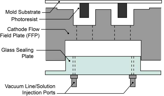 |  |
| Figure 10. Porous polymer fabrication assembly showing an expanded view of the mold (~800 μm photoresist) and glass sealing plate. A top mold limits in-channel polymerization to desired regions. The glass sealing plate extends partially into the depth of the WSS chamber, allowing room for a thin interfacial layer (200 μm) of HEMA-co-EDMA. | Figure 11. Preliminary attempt at mold release method using ~100 μm SU-8 features. Mold release achieved using N2 pressurization. |
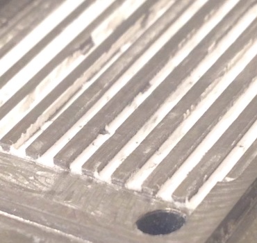 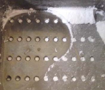 | 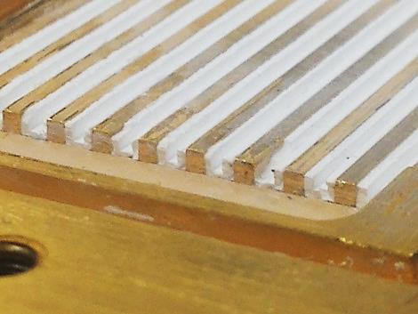 |
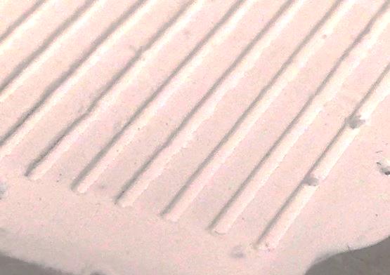
| Figure 12. In-channel porous polymer wicks produced using the SU-8 mold (left); through-hole porous polymer wicks on the backside (right). | Figure 13. In-channel porous polymer wicks produced by machining |
Before implementing the test plan for second generation prototype characterization, a new test station layout was devised. Like the original test apparatus, equipment to regulate temperature, gas pressure/flow rate, and relative humidity are required along with a suite of electrochemical data acquisition equipment and software. Since the new design features inlet and outlet ports for hydrogen and oxygen, the test apparatus was altered to provide the options of closed-ended pressure control or openended mass flow control for purging, MEA conditioning, and standard operation. In addition, humidifiers were added in-line to provide for the initial hydration of the MEA to reduce the variable initial transient hydration time, Figure 2. By adding this component it was hoped that the experiments could be run under more consistent conditions. Three types of tests were planned to establish prototype performance: a discharge conditioning procedure (measuring current density at different load voltages over time), discharge operation (measured voltage at given load current density), and charge operation (measured current density at given applied voltage). Due to issues observed during MEA conditioning and discharge testing, experiments were stopped short. The MEA exhibited a high resistance or low current flow. This could have been due to poor contact between the GDL and the MEA, poor wetting of the MEA or a damaged MEA with micro pores allowing for gas leakage. During the testing the operating voltage (V) was measured as a function of current density (j). Current density was increased from 0 to 1 A•cm-2 in 0.002 A•cm-2 increments. Due to repeated observations of poor MEA re-conditioning performance during the control case discharge tests, further testing was postponed to investigate. Repeated measurements of the open-circuit voltage (OCV) after MEA re-conditioning showed no signs of performance improvement. Initially, with a new MEA installation, OCV was measured around 1.07 V. Repeated conditioning on this MEA resulted in a final reduced open-circuit voltage of 0.947 V. Installation of a replacement, unconditioned MEA stabilized at 0.998 V OCV after a break-in procedure. The new system has in-line gas humidifiers which should provide appropriate wetting of the MEA. It is hypothesized that the low OCV was likely a result of poor interfacial contact pressure, resulting in a large electrical contact resistance. From testing at 65 °C, 5 psig H2/O2, and 90 %RH, extremely poor discharge testing (producing 0.3 A•cm-2 maximum current output) results forced a shutdown of the experiments to determine root-cause of observed issues. The project concluded with an attempt to quantify the clamping pressure on the MEA based on the sealing for the phase two design. Although we gathered some information we did not have time to remanufacture the flow field plate.
Conclusions:
There are three major advancements as a result of the Phase II of the project: the water transport calculation, the Phase II design, and the porous polymer fabrication process. The second generation prototype has been designed and its components fabricated based on observations/analysis of the first generation prototype. The new design implements a shorter transport distance within the porous wicks as well as a two-stage gas sealing design and improvements in the pressurization and purging system. The newly designed passive management layout was successfully fabricated. After initial attempts using an SU-8 mold were unsuccessful, careful machining was effective in producing the porous polymer consistent with the original geometry.
At this time we were unable to quantify the round trip efficiency of the system and therefore it is not possible to determine the lifecycle cost or the benefit to people, prosperity and the planet. The system is still in a research status and it is too early to be implemented in field testing. It is still an open question whether the porous wick structures have the capability of providing enough water transport to the membrane in balance with the electrical load requirements. The water transport needs to be sufficient under both the electrolysis and power generation processes. This may not be possible without active management of the water transport. Without appropriate management, the water transport may become the rate limiting step and generate higher system losses. Although some of the work under this grant touched up on these issues an integrated dynamic model of the process is required and was out of the scope of the current work.
Recommendations include expanding work to focus within three primary areas: direct measurement of the porous polymer water transport under varying pressure conditions, mechanical system design improvements to control the clamping pressure, and an integrated model for mass and heat transport under varying conditions. In the first area we were able to manufacture some porous plugs but the pressure and flow testing was inconclusive. From a system design perspective, a detailed system clamping pressure analysis can be helpful in establishing the source of poor operational performance. We performed some mechanical testing of the loads and compression of the gasket materials. Following this determination, further experiments can be planned to establish the true performance metrics of the fuel cell prototype. Lastly, a complete semi-analytical model coupled with numerical simulations can offer insight into fuel cell operation prior to fabrication.
References:
- [1] Zawodzinski, T. A., Derouin, C., Radzinski, S., Sherman, R. J., Smith, V. T., Springer, T. E., and Gottesfeld, S., 1993, "Water Uptake by and Transport Through Nafion 117 Membranes," Journal of the Electrochemical Society, 140 (4), pp. 1041-1047.
- [2] Strickland, D. G., and Santiago, J. G., 2010, "In situ-polymerized wicks for passive water management in proton exchange membrane fuel cells," , 195(6), pp. 1667-1675.
Journal Articles:
No journal articles submitted with this report: View all 4 publications for this projectSupplemental Keywords:
proton exchange membrane fuel cell (PEMFC), unitized regenerative fuel cell (URFC), photovoltaic (PV), fuel cell energy systems, energy storage, renewable energy, innovative technology, pollution prevention, environmental sustainability, Passive Unitized Regenerative Fuel Cell (PUReFC), polymer wicking structureProgress and Final Reports:
Original AbstractP3 Phase I:
Regenerative Fuel Cell for Off-Grid Renewable Energy Storage | Final ReportThe perspectives, information and conclusions conveyed in research project abstracts, progress reports, final reports, journal abstracts and journal publications convey the viewpoints of the principal investigator and may not represent the views and policies of ORD and EPA. Conclusions drawn by the principal investigators have not been reviewed by the Agency.