
Grantee Research Project Results
2013 Progress Report: Passive Unitized Regenerative Fuel Cell (PUReFC) for Energy Storage in Off-grid Locations
EPA Grant Number: SU835288Title: Passive Unitized Regenerative Fuel Cell (PUReFC) for Energy Storage in Off-grid Locations
Investigators: Fabris, Drazen , Lele, Sandeep , Pimentel, Ross , Sizemore, Michael , Zalawadia, Sutyen , Tabrizi, Abdie , Krishnan, Shoba , Schwartz, Jeff
Current Investigators: Fabris, Drazen , Lele, Sandeep , Sizemore, Michael , Krishnan, Shoba
Institution: Santa Clara University
EPA Project Officer: Hahn, Intaek
Phase: II
Project Period: August 15, 2012 through August 14, 2014 (Extended to August 14, 2015)
Project Period Covered by this Report: August 15, 2012 through August 14,2013
Project Amount: $89,023
RFA: P3 Awards: A National Student Design Competition for Sustainability Focusing on People, Prosperity and the Planet - Phase 2 (2012) Recipients Lists
Research Category: Pollution Prevention/Sustainable Development , P3 Awards , P3 Challenge Area - Air Quality , Sustainable and Healthy Communities
Objective:
Develop a portable, autonomous, and unitized regenerative fuel cell capable of continuous, sustainable energy to meet energy demands in off-grid applications. When coupled with a photovoltaic cell, the system will manage energy supply and demand to ensure uninterrupted renewable power. The regenerative fuel cell leverages innovative capillary wicking structures for simplified and efficient performance.
Progress Summary:
The findings of this report focus primarily on testing performed to determine the significance and root cause of previously measured results. The analysis includes additional transient discharge testing, contact resistance measurements, engineering estimations of water transport, and porous media characterization. Designs for a revised prototype are also included in this report.
Transient Discharge Testing: Additional testing of PUReFC was needed to determine the repeatability of current density decay observed in Phase I testing. The cell was tested at 0.2 V, 0.4 V, and 0.8 V for 8 hour intervals each with operating current recorded over time. Vacuum was used prior to each test to improve experimental repeatability. The data shows a general trend of long term performance stabilization at the expense of reduced power output. The short term transient behavior was also investigated (Figure 2). Selected results are shown below:
Figure 1. Constant voltage transient discharge testing at 0.2V
loading. Curent density (f) show on y-axis.
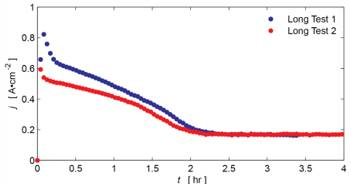
Figure 2. Transient discharge behavior at 0.2V loading. Current
density (f) shown on y-axis.
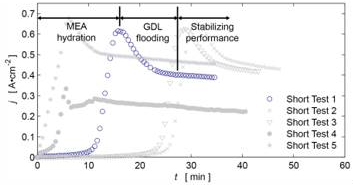
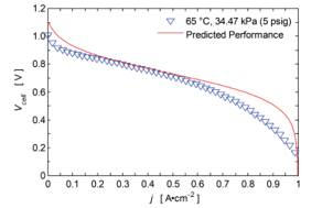
The current density curves in Figure 2 initially exhibit a stage of rapid current density increase as the membrane electrode assembly (MEA) re-hydrates after the vacuum procedure. This is consistent with rising proton conductivity as a result of increased water content[1]. It is hypothesized that the current density degradation that follows the initial behavior is associated with flooding of the cathode gas diffusion layer (GDL). The hydrophilic GDL saturates and causes an increase in gas transport resistance, resulting in a reduced reaction rate. This hypothesis also fits well with measured discharge polarization curves in which GDL saturation may be causing additional concentration loss at higher current densities (see Figure 3, 0.6-1 A•cm-2).
Figure 3. Discharge polarization curve (~10 min span).
Contact Resistance Testing: In the corrosive electrochemical environment of the fuel cell, raw titanium oxidizes quickly—creating a need for a corrosion resistant layer (Au). From repeated testing and disassembly the titanium flow plates exhibited delamination of their gold layers, allowing TiO2 formation. To determine the significance of oxidized titanium contact resistance, a four-wire method was employed to make measurements. Four-wire techniques, which use independent voltage measuring wires and current applying wires, are used for low resistance measurements. A negligible difference in resistance between gold plated and fully delaminated flow field plates (0.008 Ω) indicates that the titanium oxide layer added insignificant contact resistance relative to the total cell resistance (0.4259 Ω).
Engineering Estimations: Due to observed flooding in the cell anode after 8 hour discharge testing, the internal water transport balance was investigated. Across the membrane, electroosmotic drag and back diffusion are the two sources of water transport2. Water back diffusion is driven by the concentration gradient across the membrane and electro-osmotic drag is driven by the reaction rate. As water accumulates at the cathode, the magnitude of the concentration gradient increases eventually leading to diffusion overpowering electro-osmotic drag. The anode flooding is a result of this imbalance. Furthermore, due to the accumulation of water at the cathode it can be hypothesized that the anode flooding is due to insufficient wick transport. Engineering calculations were performed for various current densities to estimate the maximum supported water partial pressure differences across the membrane. These differences can be used to determine the necessary water transport rates that the wicks need to provide to ensure stable long term cell operation.
| j {A.cm-2} | 0.1 | 0.2 | 0.3 | 0.4 | 0.5 | 0.6 | 0.7 | 0.8 | 0.9 | 1.0 |
| ~∆P {Pa} | 400 | 1000 | 1800 | 1800 | 2600 | 3700 | 5600 | 7100 | 10000 | 12000 |
For the cse of non-functional wicks, the cathode flooding times were calculated for various current densities. These calculations demonstrate the time for complete shutdown.
| j {A.cm-2} | 0.1 | 0.2 | 0.3 | 0.4 | 0.5 | 0.6 | 0.7 | 0.8 | 0.9 | 1.0 |
| ~t {min} | 2675 | 1338 | 892 | 669 | 535 | 446 | 382 | 334 | 297 | 268 |
Porous Media Characterization: In order to better understand flow dynamics in the wicking structures, mercury intrusion porosimetry analysis is used to determine pore size distribution, mean pore diameter, and median pore diameter. This analysis was outsourced to Porous Materials Inc. in Ithaca, NY and yielded: 9.5593 μm median pore diameter (based on volume), 7.7674 μm median pore diameter (based on surface area), and 8.5524 μm average pore diameter.
Design Revisions: The refined sealing system uses two offset seals at the membrane electrode assembly (MEA) to prevent gas interaction. The flow field plates, gas diffusion layers (GDLs), and MEA will be clamped using machine screws to create a sub-assembly. To prevent electrical shorting, ceramic machine screws are used for the sub-assembly. The design revisions also incorporate exhaust manifolds for both gases which can be plugged for nonrecirculating operation.
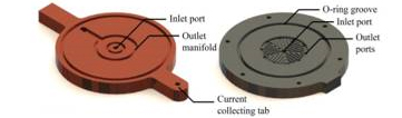
Figure 4. Cathode flow field plate (top), gas
diffusion layer (GDL), membrane electrode
assembly (MEA), and anode flow field plate
(bottom).
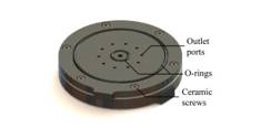
Figure 5. Current collector deisgn shown on left. Anode flow field
plate (H2) shown on right. The exhaust manifolds are integrated
into both the flow field plate and current collector.
Future Activities:
Transient Discharge Testing:The expected decay in current densities was verified by additional voltage control testing.Figure 1-4reveal details about transient current density performance. In Figure 2 the initial transient performance is likely due to membrane hydration. The tail ends of the plots demonstrate some degree of stabilization in current density. The rapid loss in operating current is most likely due to flooding of the internal gas diffusion layers (GDLs).
Contact Resistance Testing:The measurements revealed that TiO2did not contribute significantly to the overall system resistance.
Engineering Estimations:These estimates will be used to improve wick design and fabrication. The pressure calculations give an idea of the required wick transport rates needed to maintain stable long term operation.
Porous Media Characterization:The results of porosimetry testing compared well to the original assumed pore diameter (7 μm). This information can be used to more accurately determine wick flow parameters including capillary pressure and maximum supported transport rate.
Design Revisions:The refinements made towards the sealing system will help prevent gas crossover during operation.
References:
[1]Zawodzinski, T. A., Derouin, C., Radzinski, S., Sherman, R. J., Smith, V. T., Springer, T. E., and Gottesfeld, S., 1993, "Water Uptake by and Transport Through Nafion 117 Membranes," Journal of the Electrochemical Society,140 (4), pp. 1041-1047.
Journal Articles:
No journal articles submitted with this report: View all 4 publications for this projectSupplemental Keywords:
proton exchange membrane fuel cell (PEMFC), unitized regenerative fuel cell (URFC), photovoltaic (PV), fuel cell energy systems, energy storage, renewable energy, innovative technology, pollution prevention, environmental sustainability, Passive Unitized Regenerative Fuel Cell (PUReFC), polymer wicking structureProgress and Final Reports:
Original AbstractP3 Phase I:
Regenerative Fuel Cell for Off-Grid Renewable Energy Storage | Final ReportThe perspectives, information and conclusions conveyed in research project abstracts, progress reports, final reports, journal abstracts and journal publications convey the viewpoints of the principal investigator and may not represent the views and policies of ORD and EPA. Conclusions drawn by the principal investigators have not been reviewed by the Agency.