
Grantee Research Project Results
Final Report: "Collaborative Proposal" On Optimal-Control Strategies Based On Comprehensive Modeling And System-Interaction Analyses For Energy-Efficient And Reduced-Emission Fuel-Cell-Energy-Conversion Technologies For Hybrid Stationary And Non-Stationary Applications
EPA Grant Number: R831514Title: "Collaborative Proposal" On Optimal-Control Strategies Based On Comprehensive Modeling And System-Interaction Analyses For Energy-Efficient And Reduced-Emission Fuel-Cell-Energy-Conversion Technologies For Hybrid Stationary And Non-Stationary Applications
Investigators: von Spakovsky, Michael R. , Nelson, Douglas , Leo, Donald J. , Mazumder, Sudip K. , McIntyre, Chuck , Herbison, Dan
Institution: Virginia Tech , Synopsys Inc. , University of Illinois at Chicago
EPA Project Officer: Aja, Hayley
Project Period: June 1, 2004 through May 31, 2007 (Extended to December 31, 2007)
Project Amount: $200,000
RFA: Technology for a Sustainable Environment (2003) RFA Text | Recipients Lists
Research Category: Nanotechnology , Pollution Prevention/Sustainable Development , Sustainable and Healthy Communities
Objective:
1.1 Background
Fuel cell systems (FCSs) are seen as more environmentally friendly and energy efficient than their primary fossil-fuel counterparts and have a high potential for playing a significant role in the energy economy. Proton Exchange Membrane Fuel Cell (PEMFC) systems are one of the leading candidates in alternative energy conversion devices for transportation and distributed and portable power applications. Such systems (see Figure 1) typically consist of a fuel processing subsystem (FPS), which in a transportation application may be on- or off-board; a fuel cell stack subsystem (SS) with appropriate water-, air-, and thermal-management subsystems; a powerelectronics and power-conditioning subsystem (PES); a work recovery and air supply subsystem (WRAS); and some type of energy buffering both for electricity and fuel. Since these subsystems have different physical characteristics (i.e., thermodynamic, kinetic, geometric, temporal, etc.), their integration into a single unit makes the process of dynamic system synthesis/design and operation/control highly complex.
Thus, the optimal synthesis/design and operation/control of FCSs requires advanced techniques for being able to determine the syntheses/designs and dynamic operating stages of such systems which make them technically and economically viable, since FCSs are highly non-linear systems that have a number of reliability issues (e.g., catalyst poisoning, structural degradation, and temperature and pressure limitations) which must be addressed in order to avoid system failures. In addition, it is very important to synthesize/design and control the systems intelligently to not only avoid such failures but as well obtain optimal system operation across an entire load spectrum both in terms of maximizing energy savings and minimizing environmental effects. The problem is that the process very often used for system synthesis/design optimization is one based on a single, full-load condition at steady state, since it significantly simplifies system optimization. This typically results in over-/under-estimated solutions for synthesis/design and leads as well to non-opti-
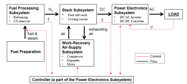
Figure 1. Schematic of a general PEMFC system for stationary applications.
mal solutions for operation/control. Thus, a more comprehensive synthesis/design and operational/control optimization process is required which takes into account part- as well as full-load conditions for satisfying an optimal efficiency/minimum-cost/minimum-environmentaleffect objective.
Of course, a difficulty that arises with a more comprehensive approach is that the number of possible system configurations and technologies that could possibly meet the designer’s objectives optimally may be large. In addition, the system may need to be developed taking into account both the transient and environmental effects on system performance. Thus, the difficulty of developing the entire system via the formulation of a single optimization problem in which the optimal synthesis/design and operation/control of the system are achieved simultaneously is great and rather problematic due to the complexities involved. These complexities are further heightened with the introduction of uncertainty analysis into the problem, transforming the problem from a purely deterministic one into a probabilistic one. Typically system/component models are treated deterministically, even though input values can have significant uncertainties due to direct sources such as computational errors and indirect ones such as load profiles and fuel costs (Kim, 2008). These uncertainties inevitably propagate through the system to the outputs. Thus, uncertainties, system complexity and non-linearity, and large numbers of decision variables quickly render the single optimization problem unsolvable by conventional single-level optimization strategies. Sophisticated multi-level ones (i.e., decomposition strategies) can, however, help overcome these difficulties and facilitate the optimization process (Munoz, 2000; Rancruel, 2005; Kim, 2008; Wang, 2008, etc.). This is done by breaking the large-scale optimization problem down into a set of approximately equivalent smaller optimization problems in order to facilitate the optimization procedure.
As to the quantification of uncertainties, traditional probabilistic approaches (e.g., Monte Carlo simulation) are untenable since their computational burden coupled with that which already exists due to the large-scale optimization with decomposition renders such methods impractical. On the other hand, the use of approximate probability methods such as the response sensitivity analysis (RSA) method may be possible since their computational burden is orders of magnitude less. The applicability of this and other approximate methods have been examined here to determine their applicability to energy system development and to evaluate how much uncertainties influence the system synthesis/design and operation/control optimization results.
An additional consideration is control. In order to achieve the gains both in terms of energy savings and pollutant emissions, it is important to synthesize/design and control the FCS intelligently. As mentioned above, an often used approach is to synthesize/design (with or without formal optimization techniques) the system first using steady state operation with high efficiency/low life cycle cost at full load. After the synthesis/design is fixed, the control subsystem is designed for the purpose of dynamic operation. The design of the controls is limited to finding appropriate values of the controller parameters, with no real consideration of the effects of the controller(s) and system dynamics on system synthesis/design. However, when transient regimes happen quite often such as in small power units and system start-up, they may be quite important for the process of system development. For example, Rancruel (2005) and Rancruel and von Spakovsky (2005, 2004) take into account not only the dynamic operation of a Solid Oxide Fuel Cell (SOFC) system during the process of synthesis/design optimization but its optimal control architecture as well with individual PID controllers. They show that optimally and simultaneously synthesizing and designing the system as well as its control architecture leads to higher system efficiencies and lower emissions across the entire load spectrum and does so in part by managing each subsystem’s response to effectively deal with load-fluctuations and load-following issues. It also does so by ensuring that the optimal component and subsystem characteristics match those of the optimal control architecture.
The question arises, however, as to the adequacy of a set of individual PID controllers when indeed the variables to be controlled represent a set of multi-outputs dependent on a set of multiinputs. To address this, the work reported here uses state space instead of the classical PID control approach in a looped set of optimizations to illustrate the effect of the control system on the synthesis/design optimization and to develop a set of optimal multi-input, multi-output (MIMO) controllers consistent with the optimal synthesis/design of the FCS. It is shown that these MIMO controllers correspond to the ones found in a non-looped optimization in which the gains for the controllers are part of the decision variable set for the overall synthesis/design and operation/control optimization.
1.2 Objectives
The overall goal of this project was to develop an enabling design approach for use in the development and control of PEMFC technologies. The major objectives envisioned were the following:
-
Develop, implement, and validate a comprehensive set of fully transient system/subsystem/component thermodynamic, kinetic, geometric, and cost models for a PEMFC system comprised of three subsystems: a FPS, SS, and WRAS; note that work on the PES was part of the effort presented in a separate report by Mazumder et al. (2008) at the University of Illinois at Chicago (UIC);
-
Perform a parametric sensitivity analysis of the proposed system configuration to determine if it is adequate or in what ways it needs to modified;
-
Develop realistic load profile scenarios for various types of stationary distributed energy systems;
-
Understand and then develop an integrated approach for applying stochastic modeling techniques and uncertainty analysis methodologies to the complex, highly non-linear system/subsystem/component models developed here; the excessive computational burdens inherent to traditional stochastic approaches (e.g., Monte Carlo simulation) must be resolved before such an integration is practically feasible;
-
Integrate the stochastically based uncertainty approach developed into the dynamic synthesis/design and operation/control optimization of the overall PEMFC configuration in order to optimally synthesize, design and control the system and its subsystems; such a probabilistic approach must be able to quantify the degree of uncertainty which results in a number of the key decision variables and inequality constraints as well as quantify the variability of the load profile scenarios used to optimally develop the final system configuration, component designs, and control architecture;
-
Develop an approach for conducting the planned optimizations within a multi- as opposed to single-objective framework;
-
Determine the feasibility of applying the dynamic decomposition strategy for multi-level optimization called Dynamic Iterative Local-Global Optimization (DILGO) developed in Rancruel (2005) and Rancruel and von Spakovsky (2005) to the synthesis/design and operation/control optimization of the PEMFC system using a hybrid heuristic/gradient-based optimization algorithm and compare the results with those obtained using a purely gradientbased optimization approach;
-
Understand and then develop an integrated approach for applying the state space control approach, which requires model linearity, to the highly non-linear system/subsystem/ component models developed;
-
Integrate this state space control approach into the dynamic synthesis/design and operation/control optimization of each PEMFC subsystem (FPS, WRAS, SS) in order to optimally design a set of MIMO (multi-input and multi-output) controllers, one for each subsystem or a single MIMO controller for the overall system consistent with the optimal synthesis/design and operation of the subsystem and/or system;
-
Verify whether or not optimizing the control architecture separately from the process of optimizing the system synthesis/design leads to the optimal system;
-
Develop a baseline optimal system synthesis/design based on operating at steady state and full load and use this to verify that taking into account transient operation during the optimization process indeed makes a difference;
-
Verify the difference or compatibility of the integrated state space approach developed here with that which determines the optimal control architecture using the integrated approach found in Rancruel (2005); the latter determines a set of optimal controller gains directly from a single system-wide optimization process in which the gains are part of the overall decision variable set for synthesis/design and operation/control;
-
For the dynamic synthesis/design and operational/control optimization process of the overall system, use the decomposition strategy for multi-level optimization called Dynamic Iterative Local-Global Optimization (DILGO) developed by Rancruel (2005) and Rancruel and von Spakovsky (2005) to perform the synthesis/design and operational/control optimization of the FCS and compare the results with those obtained using a single-level optimization approach;
-
Compare the deterministic results obtained with the probabilistic and multi-objective results obtained and draw appropriate conclusions.
It should be noted that all fourteen of these objectives were met. A brief description of our approach for achieving these objectives and a sampling of results are given in the following sections. A schematic depiction of our approach is given in the diagram, which appears in Figure
2. This diagram contains all the pertinent elements, information flows, and connections for the comprehensive paradigm of energy system synthesis/design and operation/control optimization under uncertainty developed, implemented, and validated during the course of our research. For a more detailed description of our work, the reader is referred to Kim (2008; http://scholar.lib.vt.edu.ezproxy.lib.vt.edu:8080/theses/available/etd-02012008-140009/), Wang (2008; http://scholar.lib.vt.edu.ezproxy.lib.vt.edu:8080/theses/available/etd-02042008-140129/), Kim et al. (2008a,b), and Wang et al. (2008a,b).
Summary/Accomplishments (Outputs/Outcomes):
The initial PEMFC system configuration minus the PES and any preprocessing of fuel for sulfur removal (see Figure 3) was developed taking into account all the equipment and energy recovery loops necessary to maximize total system efficiency consistent with minimum cost and environmental impact. The main objective of the FPS is to convert the natural gas to the hydrogen-rich reformat gas, which consists of three steps: reforming, water-gas shift, and CO clean-up to maintain the CO concentration at levels less than 10 ppm. To support the process, several additional units (i.e., a combustor, a steam generator, a heat exchanger network, etc.) are coupled with the chemical reactors used for the conversion steps. The SS consists of a PEMFC stack and a cooling cycle which controls the operating temperature of the stack. In the balance of plant (BOP) and the SS, the temperatures of a number of critical components have to be carefully controlled, and the flow and utilization of heat from several sources within the configuration have to be managed effectively in order to achieve high overall efficiency. Therefore, thermal management plays a significant role in the operation of the PEMFC system. Its major functions include maintaining the stack operating temperature in the appropriate range, bringing the hydrogen-rich reformate gas and compressed air to the desired anode/cathode inlet conditions be-
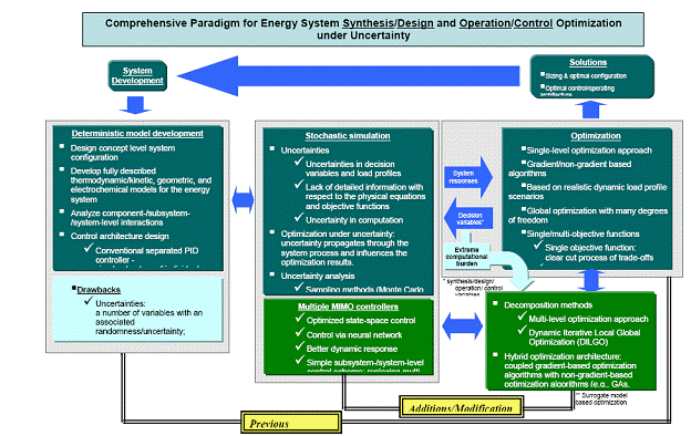
Figure 2. Paradigm for the energy system synthesis/design and operation/control optimization under uncertainty.
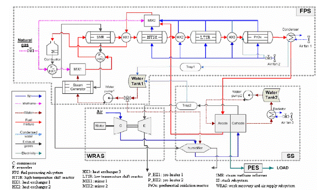
Figure 3. Initial (non-optimized) PEMFC system configuration.
fore exiting the FPS and the WRAS, respectively, and controlling the steam reformer operational conditions and the generation of the steam required for the FPS. A number of high performance heat exchangers are used within the configuration in order to meet these objectives. All component/system models were developed during the first year and a half of this project and subsequently used in the second and third years for optimizing system synthesis/design and operational/control. In addition, the proposed state space control approach and stochastic modeling and uncertainty analysis methodology were developed and then applied during the second and third years. Five of the six sections in this process summary focus on modeling, control, uncertainty analysis, optimization, and a sampling of results. Before proceeding to these sections, however, the PES and energy buffering are briefly presented in the following section.
2.1 The PES and Energy Buffering
As indicated above, the research focus at Virginia Tech has been on developing the thermal, mechanical and electro-chemical subsystems which make up the FCS and the tools required to accomplish this. Work on the PES has been conducted by the power electronics group at the University of Illinois at Chicago (UIC) headed by Prof. Sudip Mazumder and reported in Mazumder et al. (2008). Typically, the PES consists of a DC/DC converter, DC/AC inverter, and a power supply management system as well as a controller. The DC/DC converter is a power regulation unit, which provides power at the correct voltage and maintains the voltages as constant over the entire operating regime, while the DC/AC inverter provides AC power from the DC power supplied by the fuel cell stack. This electric power can then be made available to common AC power based electronic devices or to the surrounding AC utility grid. The PES must also provide power management and control by which the output of a FCS meets the load requested. A FCS’s output power must, thus, be conditioned and controlled to deliver power even under large load variations. As seen in Figure 1 above, a controller controls the entire system to satisfy the load demanded by controlling flow rates (i.e. fuel, steam, and air) and temperatures.
As to energy buffering, this may be needed in the form of battery banks and a transient reformate tank in order to reduce system response time to changing loads. Since energy buffering units increase system cost, whether or not such units are adopted must be left to the decision of the designer and may, of course, be suggested by the system synthesis/design and operation/control analysis and optimization procedure. In previous work on SOFC systems (e.g., Rancruel, 2005; Rancruel and von Spakovsky, 2004, 2005), a decision to use both a transient reformate tank and a battery bank was made. In this research, only the latter was deemed necessary, while the former was not. Work on the latter was conducted as part of the PES synthesis/design and operation/control efforts at the University of Illinois, at Chicago (Mazumder et al., 2008)
2.2 Modeling
2.2.1 System Model
During the first year and a half of this project, all component/system models were developed,
and the models and system configurations were modified through extensive system
synthesis/design analysis followed by a number of optimizations in the second year. Figure 3
shows the initial (non-optimized) configuration of the proposed FCS system with the boarders of
the FPS, SS, and WRAS indicated on the diagram. The FPS provides a hydrogen rich gas to the
PEMFC stack and consists of three main steps; a desulphurization step as a fuel (e.g., natural gas)
preparation process, a reforming step to reform the hydrocarbon fuel to a hydrogen rich gas, and a
CO removal step to reduce the CO concentration level to less than 10 ppm. Organic sulfur
contained in natural gas must be removed by the desulfurizer to prevent the detrimental effects on
the catalysts used in the FCS due to the sulfur.
As to the reforming process, steam reforming technology is modeled along with a steam generator and combustor to support the steam-methane reformer (SMR). Since the reformate gas from the SMR usually contains between an 8~10% concentration of CO, it is necessary to reduce the CO concentration below 10 ppm for safe operation of the PEMFC. To do this, a three-step CO removal unit is designed which includes high-/low-temperature water-gas shift reactors (HTSR/LTSR) and a CO-preferential oxidation (PrOx) reactor.
In the SS, a PEMFC stack based on Du Pont’s NafionTM is modeled with humidification and temperatures not in excess of 80 oC and levels of CO not in excess of 10 ppm to avoid poisoning of the electrochemical catalyst. Thermal management of the stack is addressed via use of a water cooling cycle that controls the stack’s operating temperature.
The role of the WRAS in the energy integration of the FCS is significant. It consists of a compressor, an expander, and a motor. The compressor provides compressed air to the PEMFC stack and other BOP components and is driven by an expander and motor. An electric motor is used to supply additional power to the compressor in case the power extracted from the expander is not enough to run the compressor.
Transient models for the components used in these three subsystems are not repeated here due to the complexities involved. Instead, the reader is referred to the descriptions of the thermodynamic, geometric, and kinetic models developed, implemented, and validated in this research given in the dissertation of Wang (2008; see Chapter 3 with its 31 pages of description; the pdf is found at http://scholar.lib.vt.edu.ezproxy.lib.vt.edu:8080/theses/available/etd-02042008-140129/) and that of Kim (2008; see Chapter 3 with its 49 pages of description; the pdf is found at http://scholar.lib.vt.edu.ezproxy.lib.vt.edu:8080/theses/available/etd-02012008-140009/). For more condensed descriptions, the reader is referred to Kim et al. (2008a,b) and Wang et al. (2008a,b).
2.2.2 Cost Models and Load Profiles
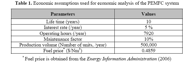
It is important to establish as accurately as possible the cost models for the FCS in order that the system’s economic performance be evaluated with any degree of confidence. Many cost models for energy system components exist in the literature, but most of them are for large-scale plant applications. Only a limited few are available for small-scale energy systems such as the 5 kWe PEMFC system of interest in this research. However, even these show significant discrepancies between real market prices and those predicted by the models. Using unrealistic cost predictions prejudice the system synthesis/design and operation/control optimization. Therefore, establishing and using appropriate cost functions for the optimization process is of importance.
In this research, cost functions for the FCS are obtained from several different literature sources (e.g., Kamarudin et al., 2006; Baratto, Diwekar, and Manca, 2005; Georgopoulos, 2002) and modified by comparing them to real market prices. Table 1 summarizes some of the primary assumptions for the economic analysis. In addition, the natural gas price used is obtained from the Energy Information Administration (2006), and an average residential price of 13.75 $/kft3 is employed for evaluating the operating costs. The capital costs, on the other hand, are based on appropriate FCS component cost functions, which relate cost to geometric variables such as volume, heat transfer area, and mass. For a detailed description to these cost functions, the reader is referred to Chapter 3 of the dissertation by Kim (2008) which can be downloaded from http://scholar.lib.vt.edu.ezproxy.lib.vt.edu:8080/theses/available/etd-02012008-140009/ and to Chapter 3 of the dissertation by Wang (2008) which can be downloaded from http://scholar.lib.vt.edu.ezproxy.lib.vt.edu:8080/theses/available/etd-02042008-140129/.
Now, in order to conduct dynamic synthesis/design and operation/control optimization of the proposed PEMFC system, it is necessary to develop a realistic, single-family, residential, electric-energy-demand, load profile. To do so, actual daily loads for the southern California area in 2006 are obtained from Southern California Edison, and the means and standard deviations of the load profiles for winter and summer are calculated. The entire load profile has been simplified into a two-day load profile in which half of the load profile represents the summer season and the rest the winter. Figure 4 shows this 48-hour load profile. To facilitate the calculation process, the peak point on the load profile has been shifted to the starting point. As seen in this figure, the mean profile represents the real power consumed during the summer and winter, and the modified profile is a simplified version of the mean used for the synthesis/design and operation/control process. Day-to-day variations are described as uncertainties in the power demand of the mean load profile; and to accommodate operation over a whole year, the modified 48-hours profile is multiplied by 182.
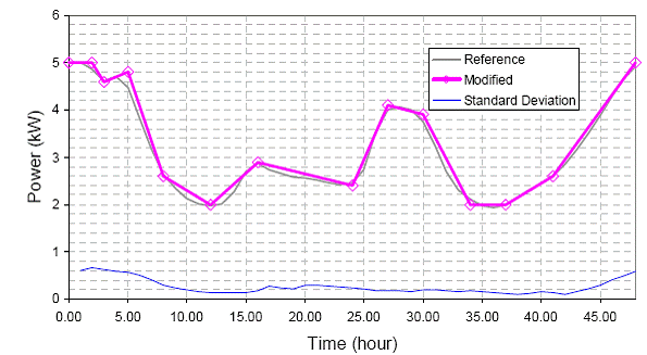
Figure 4. Approximated electricity demand profile and its standard deviation over a 48-hour, winter-summer
period in 2006 in southern California.
2.3 Control
For the energy system dynamic synthesis/design process with optimization, design of the control architecture is usually done prior to the optimization due to the fact that the system must be developed based on some representative dynamic load profile. Thus, control effects on the optimal synthesis/design and operation of the system must be studied in order to answer a number of questions, e.g., i) whether or not the controllers affect the optimization results, ii) whether or not the controllers should be optimized during the optimization process, iii) how should this be done, iv) etc.
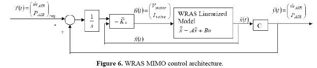
A state space control approach is used here for designing the FCS’s multiple input/output (MIMO) control architecture. Separate MIMO controllers are developed for each subsystem. To answer the questions posed above, the state space approach is used in a looped set of optimizations to design a set of subsystem controllers consistent with the optimal synthesis/design and operation of each subsystem and the system as a whole. Figure 5 illustrates this strategy as applied to the WRAS. A similar strategy is applied to all the other subsystems. The procedure is as follows:
-
Develop the state space based MIMO control architecture for each subsystem as illustrated schematically for the WRAS in Figure 5.
-
Since the application of state space control techniques is limited to linear systems, a linear representation of the highly non-linear model of each subsystem for an initial fixed synthesis/design (i.e., one with fixed synthesis/design and operation decision variable values) must be found. This is done using gPROMSTM which has the capability of providing a linearized representation (state space representation) of even highly non-linear systems at a given operating point.
-
Transfer the linearized subsystem models to MatlabTM and use the MatlabTM control toolkit and the state space representation (linearized) of each subsystem to establish the control gains and poles of each subsystem’s state-space-based, MIMO-control architecture.
-
Transfer the control gains back to the controllers in the non-linear gPROMSTM model of the subsystem and test the behaviour of the state-space-based, MIMO controllers over the entire 48-hr load profile to ensure proper behaviour at all load conditions.

Figure 5. Schematic of the looped optimization strategy applied to the WRAS.
5. If stability problems occur, return to MatlabTM in order to ‘move’ the poles for increased stability and recalculate the gains (i.e., repeat Step 3). If there are no stability problems, proceed to Step 6.6. In gPROMSTM, perform a dynamic synthesis/design and operation optimization of the subsystems/system over the entire load profile, using the particular state-space-based, MIMO controllers established in Steps 3 to 5.7. Compare the optimal synthesis/design and operation decision variable values with the initial ones on which the controller designs established in Steps 2 to 5 are based. If they are different, repeat Steps 2 to 7. If they are the same within an acceptable tolerance, the looped optimization process is finished.
The results of this looped-optimization procedure coupled to a state space approach for MIMO controller development are also compared in our research to those resulting from a dynamic synthesis/design and operation/control optimization on the subsystems/system in which the gains for the controllers are part of the decision variable set for the overall optimization. This comparison among other results is presented below. However, a brief description of the MIMO controllers for each subsystem is given next. For more details about this procedure and the controls that follow, the reader is referred to Chapter 4 of the dissertation of Wang (2008) which can be downloaded from http://scholar.lib.vt.edu.ezproxy.lib.vt.edu:8080/theses/available/etd-02042008-140129/ and to Wang et al. (2008b).
2.3.1 WRAS Control
A general schematic of the control architecture for the WRAS is shown in Figure 6. In the WRAS, an air compressor with speed control features can be used to supply different amounts of air for a wide range of power demands in order to reduce parasitic power losses. Also, to recover energy for the gases exiting the FPS, an expander, with a flow rate control, can be integrated with the compressor. Additionally, a power control of the electrical motor is necessary for this subsystem. Thus, from the aspect of controller design, there are two inputs to the WRAS: the voltage input to the motor and the current input to the downstream pressure controller. There are also two outputs from the WRAS, namely, the air flow rate and the air pressure, which satisfy the fuel cell stack requirements. In this control architecture, the voltage controls the motor shaft speed and, therefore, the compressor shaft speed. The downstream pressure controller controls the air pressure in the fuel cell stack, which is related to the output air pressure from the compressor. Therefore, with the input and output pressure of the compressor determined and with the shaft speed controlled, the air flow rate of the compressor is controlled.
2.3.2 FPS Control
As to the control architecture for the FPS, a general schematic is given in Figure 7. In this subsystem, the variables controlled are the methane and cooling air flow rates base on several key inputs such as water flow rate, methane flow rate, cooling air flow rate, and exhausting fuel flow rate from the stack, etc. The methane flow rate is controlled since it affects the hydrogen generation rate, and, thus, the hydrogen flow rate demanded by the stack. This flow rate is also affected by the steam-to-methane ratio, which is fixed during model simulation but varies during the optimization. The steam-to-methane ratio affects the reactor chemical kinetics and, thus, the
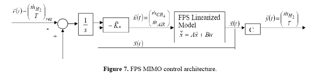
hydrogen generation rate. In addition, the cooling air flow rate keeps the reactors at the appropriate temperatures and as a consequence affects the hydrogen generation rate. In order to reduce the number of measured variables, the temperature controlled is the fuel mixture temperature before it flows through the HSTR. This ensures that all the other reactors and heat exchangers operate at the correct temperatures The flow rate ratios of cooling air among the different reactors and heat exchangers are fixed during model simulation but varied during the optimization.
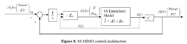
2.3.3 SS Control
Figure 8 provides a general schematic of the control architecture for the SS. As with the other subsystem MIMO controllers, it is a feedback control with integrator for the purpose of dynamic tracking. Like the other subsystems, there are multiple inputs, which include the fuel cell stack voltage and the inlet hydrogen flow rate, and multiple outputs, which include the fuel cell power and the fuel utilization (FU). To get the fuel cell to operate at the desired power requirements, the power requirements are first translated into current requirements based on the fuel cell characteristics given by the model of the fuel cell stack. The fuel cell voltage is, thus, controlled to allow the current to meet the dynamic current requirements of the load. If a fuel cell stack (at its highest power density) can not satisfy the power requirements, a bigger fuel cell is utilized in the model.
Another desired output from the fuel cell stack is FU, which is the percentage of the rate of hydrogen consumption in the stack over the inlet hydrogen flow rate. With the cell current density value, the inlet hydrogen flow rate is controlled in order to ensure that the fuel cell stack meets the FU requirement
2.3.4 FCS Control
Overall control of the FCS, as determined by the MIMO controllers described in the previous sections, is depicted in Figure 9. The purpose of these controllers is to satisfy the hydrogen flow rate requirement of the SS and allow the reactors in the FPS to work properly. One MIMO controller is used to control the methane flow rate with a fixed steam-to-methane ratio while at the same time controlling the cooling air flow rate. Another MIMO controller controls the shaft speed of the compressor via the voltage input of the motor as well as the cathode air back pressure with valve current input. Finally, the anode back pressure controller maintains the anode back pressure to be the same as that of the cathode, while another MIMO controller is used to control both the fuel cell stack’s fuel utilization and the stack’s voltage to meet the power (current) requirements demanded by the dynamic load.
2.4 Uncertainty Analysis in Dynamic Energy Systems
Computational models contain a number of variables and parameters which may have uncertainties associated with them. These uncertainties may be direct, resulting from uncertainties in the values used for these variables and parameters, or may be indirect, resulting from uncertain
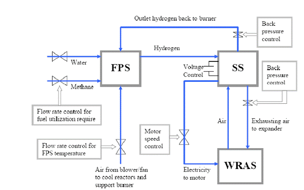
Figure 9. Overall schematic depicting where and what is controlled in the FCS system.
ties in the load profile scenarios and cost functions used to develop the system. Not incorporating these uncertainties into the modeling process can produce misleading results. Because uncertainty analysis in dynamic simulation and large-scale optimization is so computationally intensive, it may render the problem impractical to solve due to the computational resources that would be required. Thus, a simple but highly reliable methodology is required in large-scale dynamic system optimizations involving many degrees of freedom to not arrive at such an impasse. In our research, several uncertainty assessment techniques have been evaluated to assess their applicability to the dynamic synthesis/design and operation/control problems considered here. Among these are traditional sampling methods such as Monte Carlo simulation (MCS) and a number of approximate methods which include the response sensitivity analysis (RSA) method as well as fast probability integration (FPI) methods (e.g., the advanced mean-value method, first-/second-order reliability methods, and the hybrid mean-value method).
The problem with traditional sampling methods such as MCS is that they require a very large number of repeated simulations to establish the probabilistic information needed to assess the uncertainties propagated through the system to the outputs. Combined with large-scale optimization, MCS renders the overall problem computationally intractable. Because of this weakness, other modified sampling methods (e.g., the adaptive important sampling method, Latin hypercube simulation, etc.) have been proposed; but these are still inadequately modified for being able to apply them to large-scale system optimization.
The computational difficulties posed by sampling methods can be overcome by the use of RSA or FPI methods, which are approximate methods that can only approach the results generated from sampling methods such as MCS. The latter, in fact, provides exact solutions as the number of samples approaches infinity. Of course, how close the approximate method is and how robust the convergence to the sampling solution from MCS determines the viability of the approximate method. Among these methods, the RSA method and the first-order second-moment (FOSM) reliability method (an example of an FPI approach) have been adopted in our research and developed for use with the dynamic energy system synthesis/design and operation/control optimization undertaken here.
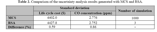
Focusing here on the first of these two approximate methods, a study is made to validate the accuracy of the proposed RSA method. Note that RSA has been used in uncertainty assessments in electronic power system analysis (Hiskens, Pai, and Nguyen, 2000; Hiskens and Alseddiqui, 2006) and for various industry decision-making problems. However, as far as we are aware, it has never been applied to the uncertainty evaluation of fuel-based energy conversion systems either for purposes of simulation or optimization. To validate the method, uncertainty analysis results using RSA are compared to the results found with MCS. Figure 10 shows the uncertainties, which occur in the outputs of the FPS using MCS. These uncertainties as well as
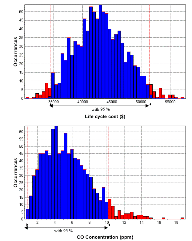
Figure 10. Probabilistic distributions of total life cycle cost and CO concentration of the FPS found by MCS.
the total life cycle cost and the CO concentration in the reformate gases at the exit of the FPS are evaluated at the optimum synthesis/design and operational points of the FPS. One thousand samples (i.e., simulations) are needed to obtain the probability distributions shown in the figure. Uncertainties in the inputs (i.e., in the given cost functions, fuel cost, and load profile) are represented by normal probability distributions. An 8% standard deviation in fuel price in 2006 is assumed based on the Energy Information Administration (2006), while a 10% standard deviation in the cost functions for the heat exchangers and chemical reactors is used. The uncertainties in the load profile are seen in Figure 4 above. The uncertainty results generated with MCS (see Figure 10) show that the total life cycle cost has a normal distribution characteristic while those for the CO concentration show a left-skewed characteristic. A comparison of these results with those found using RSA (see Table 2) show differences of less than 1%. Thus, it is concluded that uncertainty analysis results found using RSA show significant fidelity to the more precise results generated with MCS. Also, note that the number of simulations required to generate the RSA results is 3 as compared to a minimum of a 1000 required by MCS. Thus, the additional computational burden added to the synthesis/design and operational/control optimization process is minimal.
Finally, note that if the system has highly nonlinear behaviors and the input values have the characteristics of non-normal distributions, the RSA method may in fact approach the MCS results less closely. However, as seen with the validation carried out here, the fact that the system’s behavior is highly nonlinear as is the case for the FPS (and the FCS as a whole) does not appear to affect the accuracy of the method. Thus, it would seem that any inaccuracies that might be present would be due exclusively to the coupling of non-normal input distributions with non-linear system behavior. Of course, this would need to be verified and quantified although it was not done here since there is little if any physical justification for assuming that the uncertainties on the inputs is anything but normal. For more details, the reader is referred to Chapter 4 of the dissertation by Kim (2008), which can be downloaded from http://scholar.lib.vt.edu.ezproxy.lib.vt.edu:8080/theses/available/etd-02012008-140009/ and to Kim et al. (2008a).
2.5 Optimization
Three things must be decided relative to the optimization in the beginning stage of system
synthesis/design and operation/control optimization. The first is what kind of optimization
algorithm (e.g., gradient-based, non-gradient-based, or hybrid) will be used for the optimization.
The second is the choice of either a single or multi-objective approach. The third is whether a
single-level or a multi-level optimization strategy is utilized. In this research, both gradient
(Wang, 2008) and hybrid (Kim, 2008) optimization algorithms have been employed. With the
former, Wang (2008) uses a single-objective approach with a multi-level optimization strategy
while Kim (2008) utilizes both single- and multi-objective approaches with a multi-level
optimization strategy.
2.5.1 MINLP Optimization Algorithms
The synthesis/design and operation/control optimization of the FCS is a typical dynamic mixed integer non-linear programming (DMINLP) problem. In the work of Kim (2008), a sequential approximate optimization (SEQOPT) algorithm, a kind of surrogate-model-based optimization (SMBO) algorithm embedded in ModelCenterTM (a product of Phoenix Integration, Inc.), is employed, because it is computationally inexpensive (relatively speaking) and effective for solving complex problems (Jansson, Wakeman, and Manson, 2007; Rikards et al., 2006; Papalambros, 2002; Audet et al., 2000). SEQOPT is a hybrid heuristic/gradient-based optimization algorithm developed by Audet at el. (2000) at Boeing. A high-level schematic of how it works is given in Figure 11. In the work of Wang (2008), a branch-and-bound gradient-based MINLP algorithm developed by Process Systems Enterprises (PSE), LTD and implemented in its gPROMSTM product is utilized.
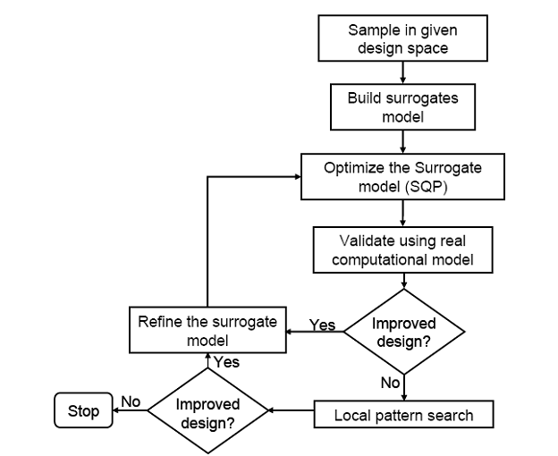
Figure 11. A high-level schematic of the SEQOPT algorithm.
2.5.2 Multi-objective Optimization
As to the single-objective optimizations implemented here, they are based on a so-called thermoeconomic objective which accounts both for the capital investments associated with the equipment used by the FCS and the cost of the fuel required to operate the FCS. Such an objective straightforwardly combines equipment and efficiency considerations directly into a single-objective function. It is assumed that each consideration is equally weighted relative to the other. This single-objective function is then optimized with and without uncertainty considerations. Details of the single-objective approach are found in Kim (2008), Kim et al. (2008a,b), Wang (2008), and Wang et al. (2008a,b).
Multi-objective optimizations, as found in Kim (2008), are also conducted here since, in general, the optimal synthesis/design and operation/control with respect to a single cost objective may not be sufficient for pointing out solutions with a higher system efficiency (and/or lower environmental effect), which, in spite of small increases in total cost, result in much more interesting syntheses/designs (e.g., based on energy and environmental policies or regulations which must be met). Thus, the investment costs and efficiency objectives are typically in conflict with each other (i.e., increasing system efficiency causes an increase in investment costs and vice versa) so that finding all of the optimal solutions that satisfy the multiple objectives simultaneously is of interest.
Execution of a multi-objective optimization results in a space called the Pareto domain (see Figure 12) of possible synthesis/design and operation/control solutions which can be traded off against one another. The Pareto approach is used to find the optimal set of decision variable values, since the concepts of Pareto dominance and optimality are straightforward tools for determining the best trade-off solutions among conflicting objectives. In the past Genetic, algorithms (GAs) have been used widely for searching the Pareto optimal solutions of multiobjective optimization problems because these optimization techniques by their very nature generate a set of solutions (i.e. called a population) to carry out the required tasks. However, because GAs are computationally expensive, multi-objective optimizations have not been applied widely to energy system synthesis/design and operation/control.
An efficient alternative to the GA is the SEQOPT method used in our research since it is much less computationally expensive. With this method (or for that matter any other), the optimizer searches the solution space based on a single objective by treating the other objective function as a constraint, followed by the optimization of the objective function treated as a constraint in the previous step and the previous objective function now treated as a new constraint. This process of optimization continues back-and-forth until no improvement occurs. During this iterative process, each single optimization provides one optimum solution with a set of feasible solutions, and the sum of the set of feasible solutions of each run provides the Pareto set and domain as seen in Figure 12. For more details about this approach, the reader is referred to Kim (2008; http://scholar.lib.vt.edu.ezproxy.lib.vt.edu:8080/theses/available/etd-02012008-140009/) and Kim et al. (2008a).

Figure 12. Pareto set/domain in a multi-objective function space.
2.5.3 Multi-level Optimization
Multi-level optimization strategies (i.e., decomposition strategies) facilitate the optimization process by breaking a large-scale optimization problem down into a set of approximately equivalent smaller optimization problems in order to facilitate the optimization procedure. Types of decomposition include disciplinary, conceptual, time, and physical. Only the latter is used in this research. Decomposition approaches are very effective for facilitating the optimization of dynamic systems which have highly nonlinear characteristics with a large number of degrees of
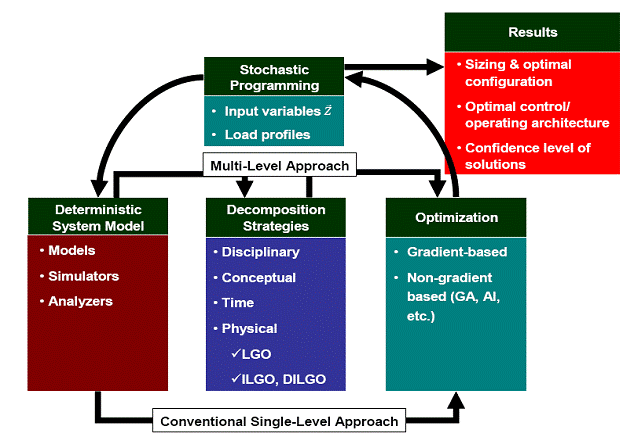
Figure 13. Schematic of the general deterministic single- and multi-level optimization process under uncertainty.
freedom. Figure 13 shows a schematic of the general single- and multi-level optimization process in which the decomposition acts as an interface between the deterministic model and the optimizer. The various physical decomposition techniques in the literature can, in general, be classified as methods of either local-global optimization (LGO) or iterative local-global optimization (ILGO). A dynamic version of the latter, DILGO, also exists. Both ILGO and DILGO have been developed by the PI and his graduate students over the last decade and their effectiveness validated by the energy system synthesis/design and operation/control optimization of high performance aircraft and SOFC/PEMFC systems (Muñoz, 2000; Muñoz and von Spakovsky, 2000a,b; Georgopoulos, 2002; Rancruel, 2003, 2005; and Rancruel and von Spakovsky, 2003, 2005).
With the LGO approach, two levels (i.e., the subsystem- or unit-level and the system-level) of optimization are implemented instead of a single-level. At the unit level, an optimization for each unit (subsystem) and each set of values of coupling functions between units (subsystems) is carried out. These optimization results are, then, used in a system-level optimization using the coupling functions between units as decision variables. This approach has the advantage of breaking a large-scale optimization problem down into smaller unit-level problems. However, it is computationally expensive because each unit-level optimization must be carried out independently many times within the system-level optimization problem resulting in a set of nested optimizations.
Such nesting can be eliminated by recognizing that the system-level information of optimizing the system-level objective with respect to the coupling functions can be embedded directly into the unit-level objectives. Munoz and von Spakovsky (2000a,b) recognized this in developing their iterative local-global optimization (ILGO) approach, which embeds this information at the local level in the form of gradient (i.e., shadow price) information of subsystem responses to variations in the coupling functions that in turn represent subsystem-tosubsystem interactions associated with strictly system-level optimization degrees of freedom. The result is a set of system-level, unit-based optimization problems, which can be optimized independently of one another with some minimal iteration to ensure that the solution converges to the system-level optimum. A dynamic version of ILGO, DILGO, was also developed by Rancruel and von Spakovsky (2005) and validated using a dynamic SOFC based auxiliary power unit (APU) synthesis/design and operation/control optimization problem. It is DILGO which is used in this research because it is the most suitable for the type of large-scale dynamic energy system synthesis/design and operation/control optimization problem tackled here. For more details of the mathematics and application of this approach, the reader is referred to Kim (2008; http://scholar.lib.vt.edu.ezproxy.lib.vt.edu:8080/theses/available/etd-02012008-140009/), Kim et al. (2008b), Wang (2008; http://scholar.lib.vt.edu.ezproxy.lib.vt.edu:8080/theses/available/etd-02042008-140129/), and Wang et al. (2008a).
2.6 Sampling of Results
2.6.1 Optimal Control: Looped and Non-Looped Dynamic Optimizations
Results for the looped-optimization procedure coupled to a state space approach for the MIMO controller development described in Section 2.3 above are presented for the WRAS in this section. They are then compared to the MIMO controller which results from a dynamic synthesis/design and operation/control optimization of the WRAS in which, instead of using state space, the controller gains are part of the decision variable set for the overall optimization.
The looped optimization uses the procedure outlined in Figure 5 above. Results for the optimum looped and non-looped, total life cycle (TLC) costs for the WRAS are presented in Table 3 and in Figure 14. The first four columns of the table and the red bars in the figure present the results for the looped optimization in which controller gains remain constant during each iteration and are determined prior to each iteration by the use of the state space approach. After four iterations, the looped optimization results converge, i.e. further changes in the controller gains have no effect on the optimal synthesis/design of the WRAS. The fourth column in Table 3 and the blue bar in Figure 14 represent the non-looped optimization results; and as can be seen, these are almost identical to those for the looped optimization.
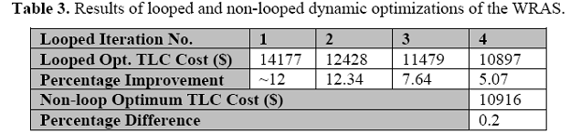
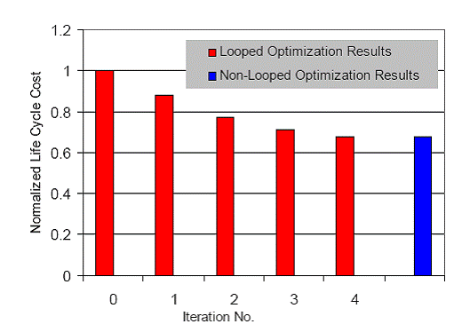
Figure 14. Results of the looped and non-looped optimizations.
As can be surmised from these results, the controllers act as limitations on the optimization. During dynamic tracking, the closed-loop control architecture is not stable for all possible values of the optimization synthesis/design decision variables. Thus, in each iteration, the optimization only finds the optimum system synthesis/design, which can still be controlled by the controllers. This is clearly illustrated in Figure 15, which shows that as the flow rate requirements from the stack change, the WRAS dynamic response, i.e., the settling time and overshoot of the flow rate, are different between the optimal WRAS found in iteration 4 and the optimal subsystem found in iteration 1. In contrast, when the gains of controllers are treated as part of the decision variable set for the overall optimization as is done in the non-looped optimization, the results show only minor differences between the end results of these two approaches. This indicates that, during the dynamic synthesis/design and operation/control optimization process, controller gains should be treated as decision variables together with the synthesis/design and operation decision variables, else the controllers become constraints on system development even though the changing of controller gains has only a minor effect on the objective function, i.e., on the system life cycle cost.
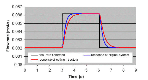
Figure 15. Comparison of dynamic responses to the changing of the flow rate requirement between the original and the optimal WRAS in the same optimization loop.
2.6.2 Dynamic versus Steady-State Optimizations
In this section, a comparison is made between the optimal results obtained from a dynamic synthesis/design and operation/control optimization and those obtained when only a single steady state condition at the most demanding load point, i.e., full load, is considered. The comparison is made in order to determine whether or not the added difficulty of modelling and optimizing dynamically is in fact worth the effort.
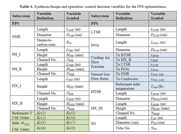
To make the comparison, the FPS is used due to its complexity and highly nonlinear behaviour. It is optimized dynamically with the synthesis/design and operation/control decision variables listed in Table 4. Note that the cells in the table shaded in light blue are the operation decision variables while those shaded in light green are the control decision variables. The FPS is then optimized at steady state using the full load condition and the same set of decision variables but minus the gains. Once this optimization is completed, the control architecture is designed (the gains determined) to operate the optimum system obtained from the steady state optimization. The optimal steady state system with controllers is then operated under the same dynamic load profile used in the dynamic optimization in order to determine the total life cycle cost. This cost is then compared with that obtained from the dynamic optimization.
The comparison is shown in Figure 16 and Table 5 along with the total life cycle costs of the initial FPS with which the optimizations begin. All three syntheses/designs are operated using the same dynamic 48-hour load profile given in Figure 4. The dynamic and steady state optimizations improve the total life cycle costs by 19% and 6%, respectively, over that of the initial FPS, with the dynamic optimization providing an improvement more than 3 times as great as that from the steady state optimization. Furthermore, it must be emphasized that the initial FPS synthesis/design was determined after a very lengthy process of modelling, simulation and analysis (no optimization), so that, for example, the 19% improvement resulting from the dynamic optimization is probably a very conservative figure.
In terms of the component syntheses/designs, the dynamic optimization results in smaller reactors due to the fact that the dynamic optimization considers the entire load profile during the
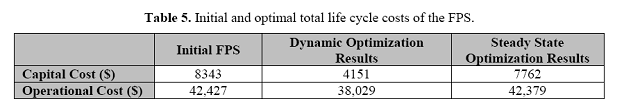
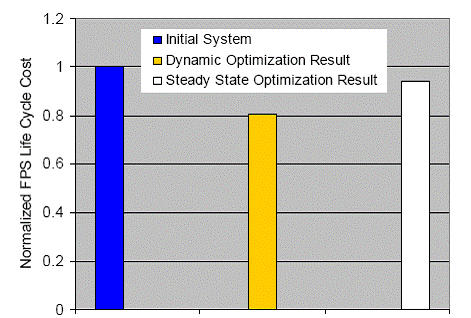
Figure 16. Total life cycle cost results for the initial FPS and the FPS dynamic and steady state optimizations.
optimization process, resulting in a set of reactors that do not reduce system efficiency much but do save on capital cost. In addition, as can be seen in Figure 17, which plots the lengths of the four reactors (SMR, HTSR, LTSR, and PrOx), the decrease in reactors sizes for the dynamically optimized FPS is dramatic even though there is a less significant drop in total life cycle costs (see Figure 16). This is due to the fact that fuel or operating costs represent a very large fraction of the total life cycle costs (see Table 5).
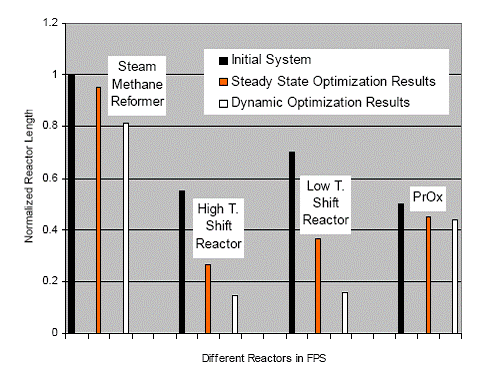
Figure 17. Comparison of the initial and optimal reactor sizes for the FPS.
Finally, it must be emphasized that the conclusions drawn here are application dependent to the extent that they are applicable to the synthesis/design of highly dynamic systems. Obviously, a base-load plant is not such a system. However, distributed power and cogeneration systems are, and the 5 kWe PEMFC system considered in this research is a prime example. Of course, these improvements must be weighed against the fact that not only does the dynamic optimization procedure takes much longer to complete (i.e., there is an order of magnitude difference), but more importantly, the time for developing the dynamic models and the dynamic optimization procedures is considerably longer as well. However, that being said, it is difficult to argue with the significantly decreased costs both in terms of capital and operation that are possible with dynamic optimization for these types of applications.
2.6.3 Multi- versus Single-objective Optimization Results
To study the multi- versus single-objective optimization results, we once more focus on the FPS. Results for the latter are given in Figure 18. The non-solid square in the figure represents the optimum total life cycle cost (i.e., $43,020), while the circles are possible outcomes or intermediate solutions of the FPS which satisfy all of the constraints. There is some confidence that this optimum is the global optimum for the FPS’s synthesis/design and operation/control since the optimization is repeated three times starting from significantly different initial points with results almost identical to the first. Nonetheless, the question arises as to whether or not a global optimum has actually been found, since the SEQOPT algorithm used for these particular results uses a surrogate model which is generated for a given set of decision variable ranges. Different ranges may predict different results. To verify if the solution is indeed a global one, a different set of decision variable ranges is used. These optimal results represented by the solid square (i.e., $42,670) are also presented in Figure 18. The second optimization result (i.e., the solid square) for the total life cycle cost is about a 0.8% improvement over the initial optimization result (i.e., the non-solid square) with a 1.65% decrease in the operating cost but a 7.3% increase in the capital cost of the FPS. The optimization is then repeated 5 more times for different sets of decision variable ranges. These results also appear in Figure 18. No further improvement is observed.
Such a procedure for determining the global nature of the solution found may, however, not be the best way of proceeding since there are no rules for adjusting the decision variable ranges. This issue can be resolved by using a multi-objective optimization approach. The multi-objective optimization is carried out by breaking the single objective function composed of capital and operating costs into two: one for capital and the other for operating costs and optimizing the objective functions individually. The first optimization is then conducted using one of these objective functions, while the other is treated as an inequality constraint. This process is then reversed for the next optimization and further optimizations are conducted by cycling back and forth between these two problems. Initially, the capital cost (i.
2004
2005 Progress Report
2006
Conclusions:
This study leads to a number of conclusions and these are summarized as follow:
1. Several uncertainty analysis methods (i.e., MCS, FPI, and RSA) have been evaluated. Based on our work, the RSA method is the most appropriate for describing uncertainties in the dynamic simulation and optimization of energy systems due to its efficiency in computation. Unlike MCS, it is an approximate method which, nonetheless, shows high accuracy when compared to MCS (a difference of less than 1% for the problems examined). Therefore, it is a very useful approach for uncertainty quantification in dynamic energy system optimization problems.
2. Our sensitivity analysis of the PEMFC system points to the highly non-linear characteristics of the system, which make solution of the system optimization problem and the design of the control architecture very problematic. The typical energy system control architecture design is based on a linearized model of the system obtained from a sensitivity analysis of the initial synthesis/design of the system. That architecture may not work correctly for other syntheses/ designs or operating conditions because of system non-linearities. Thus, the stability of the controller(s) and their design must be evaluated and updated during the system synthesis/design optimization process.
3. The efficiency of using a hybrid heuristic/gradient-based optimization algorithm (SEQOPT) for finding the global optimum point is established in this research via a comparison with the optimums found using gradient-based algorithms. The latter more easily get stuck at local minima as demonstrated by the FPS results of Wang (2008) when compared to those found by Kim (2008).
4. Uncertainty effects on the energy system synthesis/design and operation/control optimization show little effect on the objective function of operating and capital cost, yet significant effect on certain constraints (e.g., on CO concentration) during the synthesis/design and operation/ control optimization.
5. Multi-objective optimizations for energy system synthesis/design provide a number of benefits, including i) a range of possible synthesis/design solutions which can be traded off against one another and ii) a logical procedure for searching for the global optimum solution.
6. Proton exchange membrane fuel cell (PEMFC) systems with extensive energy integration promise higher average system efficiencies for distributed generation compared to conventional power generation systems. The optimum synthesis/design of the PEMFC system developed here shows a fairly steady and remarkably high overall system efficiency at 46.5% throughout the operating regime (i.e., from full load to 40% of full load) and is to our knowledge the highest of any PEMFC system efficiency reported in the literature. The primary reason is that all synthesis/design and operation/control issues are taken into account simultaneously and optimally.
7. It is demonstrated that decomposition strategies such as DILGO for large-scale energy system optimization are very useful, particularly when the overall system model with its complex control architecture and very detailed component models causes a large computational burden and frequent simulation failures during dynamic optimization.
8. A physical decomposition strategy such as DILGO makes possible a simultaneous optimization at the system level (i.e., with respect to the system’s performance and configuration) with that at a detailed component/subsystem level (i.e., with respect to the detailed geometries, capacities, and performance of the components/subsystems themselves).
9. Operating costs dominate the life cycle cost of the FCS so that minimizing the fuel consumption rate is of primary importance. Thus, the optimum synthesis/design of the FPS plays a very important role in the entire PEMFC system synthesis/design and operation/control optimization problem because most of the additional fuel consumption in the PEMFC system occurs during fuel processing (e.g., the hydrogen oxidation reactions in the CO preferential oxidation (PrOx) reactor, fuel for the combustor, poor reforming performance, etc.).
10. System efficiency is enhanced by 3.4 percentage points for the optimum PEMFC system by using an energy recovery unit. Furthermore, in the WRAS, finding the optimum design of the motor is more important than finding those of the compressor and expander since there is significant improvement in the motor design while little improvement occurs in the compressor and expander designs.
11. The optimum purchase cost of the PEMFC is highly dependent on the yearly production volume and the optimal value of $744.0/kWe for 500,000 production units per year found here is very competitive with conventional technologies in many small-scale stationary power markets. Even at 100,000 production units per year, the FCS remains competitive at $1,344.5/kWe in a number of markets. Thus, mass production of FCSs is a must for commercialization.
12. The integration of the state space control design approach for multi-inputs/outputs into the synthesis/design and operation/control optimization process is possible even for highly nonlinear, complex energy systems, particularly when coupled to the power of the DILGO decomposition strategy.
13. It is shown via the looped optimizations that the MIMO controllers in the system act as a constraint on the optimization even though they play only a minor role in the total cost of the system. Thus, either the optimal MIMO controller gains should be determined from the looped optimization procedure implemented here or directly as part of the decision variable set used in the dynamic synthesis/design and operation/control optimization of the system.
14. The integration of state space control design and the DILGO decomposition strategy provides a powerful way of gaining great insight into a system’s dynamics and the relationships which exist between each unit/subsystem and its respective decision variables.
15. Dynamic synthesis/design and operation/control optimization is useful for producing reasonably sized systems based on representative load profiles since synthesis/design and operation/control optimization at steady state and full load only typically results in overestimated solutions, i.e. larger systems and higher costs.
References:
1. Audet, C., Dennis, J. E., Moore, D., Booker, A., and Frank, P., 2000, “A Surrogate-Model-Based Method for Constrained Optimization, Proceedings of the Eighth AIAA/USAF /NASA/ISSMO Symposium on Multidisciplinary Analysis & Optimization, Long Beach, CA, Paper no. 2000-4891, AIAA.
2. Baratto, F., Diwekar, U. M., and Manca, D., 2005, “Impacts Assessment and Trade-Offs of Fuel Cell-Based Auxiliary Power Units: Part 1: System Performance and Cost Modeling,” Journal of Power Sources, 139, 205-213.
3. Energy Information Administration, 2006, “U.S. Natural Gas Prices”, http://www.eia.doe.gov.
4. Georgopoulos, N., 2002, “Application of a Decomposition Strategy to the Optimal Synthesis/Design and Operation of a Fuel Cell Based Total Energy System,” M.S. Thesis, advisor: M. R. von Spakovsky, Virginia Polytechnic Institute and State University, Blacksburg, VA.
5. Hiskens, I. A., Pai, M. A., and Nguyen, T. B., 2000, “Bounding Uncertainty in Power System Dynamic Simulations,” IEEE Power Engineering Society Winter Meeting, Vol. 2, pp 1533-1537.
6. Hiskens, I. A. and Alseddiqui, J., 2006, “Sensitivity, Approximation and Uncertainty in Power System Dynamic Simulation, IEEE Transactions on Power System, Vol. 21, No. 4, pp 1808-1820.
7. Jannson, N., Wakeman, W. D., and Manson, J., 2007, “Optimization of Hybrid Thermoplastic Composite Structures Using Surrogate Models and Genetic Algorithms,” Composite Structure, Vol. 80, pp 21-31.
8. Kamarudin, S. K., Daud, W. R. W., Som, A. Md., Takriff, M. S., and Mohammad, A.W., 2006, “Synthesis and Optimization of a PEM Fuel Cell System via Reactor-Separation Network (RSN),” Journal of Power Source, 159, 1194-1204.
9. Kim, K., 2008, “Dynamic Proton Exchange Fuel Cell System Synthesis/Design and Operation/Control Optimization under Uncertainty,” Ph.D. dissertation, advisor: M. R. von Spakovsky, Virginia Polytechnic Institute and State University, Blacksburg, VA, 2008.
10. Kim, K., Wang, M., von Spakovsky, M. R., Nelson, D. J., 2008a, “Dynamic Synthesis/Design and Operation/Control Optimization under Uncertainty of a PEMFC System,” International Mechanical Engineering Congress and Exposition – IMECE’2008, ASME Paper No. IMECE2008-68070, N.Y., N.Y., Oct.-Nov.
11. Kim, K., Wang, M., von Spakovsky, M. R., Nelson, D. J., 2008b, “Stochastic Modeling and Uncertainty Analysis with Multi-objective Optimization Strategies for the Synthesis/Design and Operation/Control of a PEMFC Fuel Processing Subsystem,” International Mechanical Engineering Congress and Exposition – IMECE’2008, ASME Paper No. IMECE2008-68065, N.Y., N.Y., Oct.-Nov.
12. Mazumder, S. K., Pradhan, S., and Burra, R. K., 2008, “Final Report: Optimal-Control Strategies Based on Comprehensive Modeling and System-Interaction Analysis for Energy-Efficient and Reduced-Emission Fuel-Cell-Systems: Power Electronics Subsystem,” final report to the US EPA, University of Illinois at Chicago, Chicago, Illinois.
13. Muñoz, J. R., 2000, “Optimization Strategies for the Synthesis/Design of Highly Coupled, Highly Dynamic Energy Systems, Ph.D. Dissertation, advisor: M. R. von Spakovsky, Virginia Polytechnic Institute and State University, Blacksburg, VA.
14. Muñoz, J. R. and von Spakovsky, M. R., 2000a, “The Use of Decomposition for the Large Scale Synthesis/ Design Optimization of Highly Coupled, Highly Dynamic Energy Systems: Part I - Theory,” ASME International Mechanical Engineering Congress and Exposition, Orlando, FL, Nov 5-10.
15. Muñoz, J. R. and von Spakovsky, M. R., 2000b, “The Use of Decomposition for the Large Scale Synthesis/ Design Optimization of Highly Coupled, Highly Dynamic Energy Systems: Part II - Applications,” ASME International Mechanical Engineering Congress and Exposition, Orlando, FL, Nov 5-10.
16. Papalambros, P., 2002, “The Optimization Paradigm in Engineering Design: Promises and Challenges, Computer-Aided Design, Vol. 34, pp 939-951.
17. Rancruel, D. F., 2005, “Dynamic Synthesis/ Design and Operation/Control Optimization Approach applied to a Solid Oxide Fuel Cell based Auxiliary Power Unit under Transient Conditions,” PhD. dissertation, advisor: M.R. von Spakovsky, Virginia Polytechnic Institute and State University, Blacksburg, Virginia.
18. Rancruel, D. F., von Spakovsky, M. R., 2004, “Investigation of the Control Strategy Development Using an Integrated Model of a SOFC Based APU under Transient Conditions,” International Mechanical Engineering Congress and Exposition – IMECE’2004, ASME Paper No. 62372, N.Y., N.Y., November.
19. Rancruel, D., 2003 “A Decomposition Strategy Based on Thermoeconomic Isolation Applied to the Optimal Synthesis/Design and Operation of an Advanced Fighter Aircraft System”, Master thesis, advisor: M. R. von Spakovsky, Virginia Polytechnic Institute and State University, Blacksburg, VA.
20. Rancruel, D. F., von Spakovsky, M. R., 2005, “Development and Application of a Dynamic Decomposition Strategy for the Optimal Synthesis/Design and Operational/Control of a SOFC Based APU under Transient Conditions,” International Mechanical Engineering Congress and Exposition – IMECE 2005, ASME Paper No. IMECE2005-82986, N.Y., N.Y., Nov.
21. Rancruel, D. and von Spakovsky M. R., 2003, “Decomposition with Thermoeconomic Isolation Applied to the Optimal Synthesis/Design of an Advanced Fighter Aircraft System,” International Journal of Thermodynamics, Vol. 6, No.3, pp. 93-105.
22. Rikards, R., Abramovich, H., Kalnins, K., and Auzins, J., 2006, “Surrogate Modeling in Design Optimization of Stiffened Composite Shells,” Composite Structures, Vol. 73, pp 244-251.
23. Wang, M., 2008, “Integration of State-Space into the Dynamic Synthesis/Design and Operational/Control Optimization of a PEMFC System,” Ph.D. dissertation, advisor: M. R. von Spakovsky, Virginia Polytechnic Institute and State University, Blacksburg, VA.
24. Wang, M., Kim, K., von Spakovsky, M. R., Nelson, D. J., 2008a, “Multi- versus Single-Level Dynamic Synthesis/Design and Operation/Control Optimizations of a PEMFC System,” International Mechanical Engineering Congress and Exposition – IMECE’2008, ASME Paper No. IMECE2008-68073, N.Y., N.Y., Oct.-Nov.
25. Wang, M., Kim, K., von Spakovsky, M. R., Nelson, D. J., 2008b, “Use of State Space in the Dynamic Synthesis/Design and Operation/Control Optimization of a PEMFC System,” International Mechanical Engineering Congress and Exposition – IMECE’2008, ASME Paper No. IMECE2008-68076, N.Y., N.Y., Oct.-Nov.
Future Activities:\
Journal publications of our results and presentations at conferences and other events are part of our future plans.
Journal Articles:
No journal articles submitted with this report: View all 8 publications for this projectSupplemental Keywords:
Sustainable Industry/Business, RFA, Scientific Discipline, TREATMENT/CONTROL, POLLUTION PREVENTION, Technology for Sustainable Environment, Sustainable Environment, cleaner production/pollution prevention, Environmental Engineering, Technology, Energy, energy technology, alternative energy source, emission controls, environmental sustainability, green design, energy conservation, clean technologies, energy efficiency, environmentally conscious design, innovative technology, modeling, environmentally friendly fuel cell power systemProgress and Final Reports:
Original AbstractThe perspectives, information and conclusions conveyed in research project abstracts, progress reports, final reports, journal abstracts and journal publications convey the viewpoints of the principal investigator and may not represent the views and policies of ORD and EPA. Conclusions drawn by the principal investigators have not been reviewed by the Agency.