POWER GENERATION USING MEGNETOHYDRODYNAMIC GENERATOR WITH A CIRCULATION FLOW DRIVEN BY SOLAR-HEAT-INDUCED NATURAL CONVECTION
Impact/Purpose:
The team in this project will model, design, and test a magnetohydrodynamic (MHD) power generation system. Electricity is produced by flowing conductive fluid through a permanent magnetic field, while the fluid flow is induced by solar heating. The goal of the project is to utilize solar energy to generate electrical power in a cheap, clean, and sustainable way. Disciplines involved in the development of the prototype power generator will include: magentohydrodynamics, solar energy collection, natural convective heat transfer, flow instability and control. Students will have hands-on experience of design, optimization, and manufacturing of innovative energy systems for sustainability of environment and economy. The project is intrinsically multi-physics and multi-disciplinary.
Description:
Objective:
In this project, solar heat is used to generate a temperature gradient in an electrically conductive fluid so that a buoyancy-driven flow and circulation will occur in an annulus flow channel. As the electrically conductive fluid passes through a magnetic field, electrical power can be generated based on Faraday’s law of induction. A generator using this mechanism is also known as a magnetohydrodynamic generator. Using solar energy in a magnetohydrodynamic generator takes the advantages of converting solar energy into thermal energy and inducing a Buoyancy-driven flow at relatively low cost. The conversion of the kinetic energy in a fluid into electrical energy is also cost effective in such a system. The project substantially contributes to the development of sustainable energy resources in Arizona, one of the places geographically abundant of solar energy in the United States of America.
The objective in the phase-I project is to build a prototype system, identify and understand major issues in such a system, and prove the feasibility of the concept of solar magnetohydrodynamic power generation. In building this system, the team has been learning and dealing with issues of solar tracking, solar concentration and heat collection, free convection and drag reduction in fluid flow, waste heat dissipation, magnetic field setting up, circuit and wiring, budget management, material procurement, project management including technical planning and scheduling, and optimization of the system considering all issues technically and economically. The project greatly helps the faculty advisors to train students, the future generation, to have a substantial understanding of the sustainability of resources on this planet and the sustainability of economy and environment.
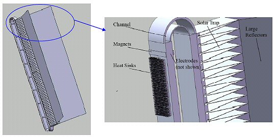
Figure 2. Finite element analysis found that there was ± 0.0278 °C across the entire surface of the inner surface of the plate.
Simply using black paint as a heat trap was brought up in our consideration. However, the current design allows injecting insulations into the triangular space between the reflectors of the solar trap, thus preventing heat loss to the surrounding. To avoid corrosion and electrical current flowing through the aluminum, the inner surface of the channel is coated with highly electrically resistive paint. After coating, the resistance of the painted layer was measured, and insulation is ensured.
The free convection and flow velocity in the right-hand side channel shown in Fig. 1 is induced by the solar heat. When the fluid flows to the flow channel on the left-hand side, it passes through multiple magnetic fields and electrical power is withdrawn. A rounded connection at the top and the bottom of the hot and cold flow channels was used to smooth the flow and reduce drag. Setting a number of magnetic fields is for the purpose of getting a multiple increment of the voltage of the electrical current generated in the system. The permanent magnetic material from some companies (The Magnet Source, United Nuclear, Amazing Magnets, K&J Magnetics, Magcraft) are surveyed and studied in order to find the best quality-to-price ratio. After testing of several types of magnets, product from K&J Magnetics is selected to be used in the prototype system. As seen in Fig.1, the heated fluid is cooled down in the left-hand side flow channel before it goes to the right-hand side channel for the next circulation. On the outer surface of the left-hand side channel heat sink fins are attached to dissipate heat. Heat sink fins are selected after surveying and comparison of products from several companies (Aavid Thermalloy, Comair Rotron, Conrad, Radian Store, and Electrical Goldmine). The working fluid has to be electrically conductive. Properties of conductivity, thermal expansion coefficient, and prices of many conductive fluids including mercury, gallium, water, sea water, as well as some acids are investigated. Sea water, environmentally benign and cheap, is selected to be used in the prototype system.
The team has conducted three types of proof-of-concept tests in parallel with the process of designing, modification, and fabrication of a prototype system as shown in Fig. 1.
In experiment I, a proof-of-concept for magnetohydrodynamic power generation using sea water was conducted. In the experiment, sea water flows down from a reservoir of 1.5 meter high through a plastic pipe of 1/2” in diameter. At different vertical height of the reservoir, sea water flows in the pipe at different velocity. Permanent magnetic elements were used for making a magnetic field. At the location of magnetic field, two electrodes were set perpendicularly to lead the voltage out from the system. A voltage of 30 mV to 130 mV was observed on an oscilloscope in the test at different flow velocity, which is simply controlled by varying the vertical distance between the two sea water reservoirs.
In the experiment II, multiple magnet fields, pairs of magnetic elements, were set in order to getting a higher voltage from the system. As shown in Fig.1 on the left-hand part, several pairs of magnets were put along the cold flow channel. This arrangement, in fact, makes a number of magnetohydrodynamic generators on one flow. The electrodes of the multiple generators are serially connected (the cathode of one generator is connected to the anode of a neighboring generator) for the purpose of getting a higher total output voltage. The test firstly observed a voltage of 5.0 mV from one generator, in which a rectangular flow channel in cross section of 1”x1” was used, and the sea water flow was forced by a fish pump. When two generators on the same flow were serially connected, an increase of the output voltage was observed, which shows a voltage of more than 10.0 mV. This means that the addition of one more generator causes increase of the voltage. This effect is still under investigation by the team, since it is a very important issue as getting high voltage from the system is very necessary.
Numerical simulation was also performed to investigate the free convection flow field at different heat fluxes for different sized channels. Figure 3 shows a typical temperature and flow field from our numerical result. From numerical results, it was found that the gap of the channel is one important parameter that has effect on the maximum available free convection velocity in the channel. At the condition of a heat flux of 600 W/m2 to the flow channel, a channel gap of 1.0 cm is selected in the prototype system. The prototype system fabrication and construction is scheduled to be fully completed on April 5th. Full test of the system using solar energy will be conducted in the period of April 6th to 16th.
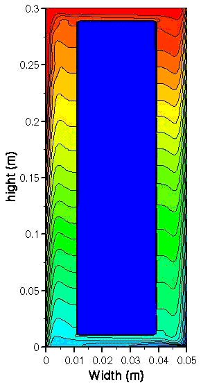
Figure 3. A typical numerical result of flow and temperature field (Heat flux is added to the left side vertical wall and is removed from the right side vertical wall. The blue area or island in the center of the domain is an insulated solid).
Conclusions:
Our preliminary test proves the concept that electrical power can be withdrawn from the flowing conductive fluid (sea water in this project) when it passes through a magnetic field. However, our system suffers a low output voltage because of the low flow velocity. The magnetic field, the distance between the two electrodes, and the flow velocity of the fluid jointly determine the voltage of the magnetohydrodynamic generator as given by the equation of Equation 1., where Voltage. is the voltage, Velocity. is the velocity of the flowing fluid, Magnetic Field. is the magnetic field, and L is the distance between the two electrodes, as shown in Fig. 4. The maximum strength available for permanent magnet is of the order of 0.1 Tesla. The fluid velocity and the distance between the two electrodes are the controllable parameters determining the generation of electricity. The velocity of the buoyancy-driven flow due to temperature gradient introduced by the solar heating is limited, and therefore using multiple electrodes and magnetic elements is considered to increase the voltage.
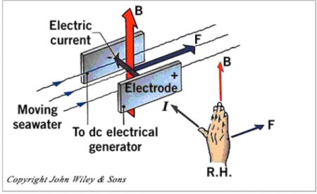
Figure 4. The orientation of flow, electrodes, and magnetic field.
The improved voltage output from using multiple magnetic fields and generators in the same circulation flow was observed in our test. However, more careful investigation is expected in our near-future experimental work.
Proposed Phase II Objectives and Strategies
Through the phase-I research and experiment, the team has gotten sufficient understanding of the practical challenges in the system. This leads to the setting of the objectives of the Phase II project. The team will conduct extensive test about the phase-I prototype system and thoroughly understand the issues of how to obtain higher voltage from the system. The conductivity of the working fluid, the distance between the two electrodes, and the distance between two magnetohydrodynamic generators are factors to be investigated in order to serially connect and wiring the multiple generators and get higher voltage output from the system. In order to export more electrical power from the fluid flow, hybrid system of magnetohydrodynamic generator combined with micro hydro turbines is considered to build in the flow circulation channels. The addition of micro hydro turbines to the system may help to extract electrical energy at the maximum magnitude.
With the hybrid power generation concept in mind, the team will develop a new system in the phase-II project. Since the phase-II project covers a period of two years, the team will be able to conduct a thorough test and eventually mature the design, fabrication, and assembly processes of an advanced hybrid power generation system with the combination of magnetohydrodynamic generator and micro hydro turbines. The new system is a scaled-up system, which will take several times of the solar heat compared to that in the phase-I project. The system will also be instrumented to have flow velocity, temperature, voltage, and current indications. Energy conversion efficiency will also be monitored.
For a smooth continuation of the project in phase-II, two junior volunteer students and four senior students will be recruited as a team starting to work on the project in the first year. In the second year, the two students who started the project from their junior year will work together with another four new senior students to carry out the project as their capstone design project. The team will have one student from optical engineering, one from electrical engineering, and four from mechanical engineering at the University of Arizona.
Record Details:
Record Type:PROJECT(
ABSTRACT
)
Start Date:08/30/2007
Completion Date:08/29/2008
OMB Category:Highly Influential
Record ID:
187263
Keywords:
SUSTAINABLE DEVELOPMENT, INNOVATIVE TECHNOLOGY, RENEWABLE, MAGNETOHYDRODYNAMIC, SOLAR ENERGY, SOLAR THERMAL COLLECTION, ENERGY AND POWER, ELECTRICITY PRODUCTION, NATURAL CONVECTION AND HEAT TRANSFER, MULTI-PHYSICS, MULTI-DISCIPLINARY,
Acronyms:
Title
:POWER GENERATION USING MEGNETOHYDRODYNAMIC GENERATOR WITH A CIRCULATION FLOW DRIVEN BY SOLAR-HEAT-INDUCED NATURAL CONVECTION
Version
:1.0
Acronym
:FEM
Acronym Meaning
: finite element method
Related Organizations:
Role
:OWNER
Organization Name
:UNIVERSITY OF ARIZONA
Citation
:Tucson
State
:AZ
Zip Code
:85721
Project Information:
Approach
:In the innovative system, a conductive fluid in an annulus circulation channel is heated up by the solar heat on the front side and is then cooled down on the back side. Consequently, the flow can circulate continuously in an annulus, as long as the warming up and cooling down processes keep to be applied, and as the result, power generation is made possible based on solar energy. The team will design and prototype a model, which is on the basis of optimization design, manufacturing techniques and materials, to convert heat from solar energy into electrical power.
Since the system using a unique concept to convert solar energy into electrical power in a relatively cheaper way, opportunities of sustainable development of using this technique for solar energy harvest are enormous. Although multi-disciplines are involved in such a system, which makes the design and analysis challenging, the manufacturing and implementation of the system is relatively easy and cost effective. To build a prototype system, the team will consider radiation heat transfer for effective collection of solar energy. Particularly, we will use analytical, numerical, and experimental approaches to study the flow field and its interaction with magnetic field, when the heat fluxes given by solar energy heating and ambient air-cooling vary in the system.
Solar energy, abundant in southern Arizona, is sustainable and clean energy. Students who participate in this project will get education and inspiration to make innovations in energy technologies especially the harvest and utilization of solar energy.
Cost
:$10,000.00
Research Component
:Pollution Prevention/Sustainable Development
Risk Paradigm
:EFFECTS
Approach
:In the innovative system, a conductive fluid in an annulus circulation channel is heated up by the solar heat on the front side and is then cooled down on the back side. Consequently, the flow can circulate continuously in an annulus, as long as the warming up and cooling down processes keep to be applied, and as the result, power generation is made possible based on solar energy. The team will design and prototype a model, which is on the basis of optimization design, manufacturing techniques and materials, to convert heat from solar energy into electrical power.
Since the system using a unique concept to convert solar energy into electrical power in a relatively cheaper way, opportunities of sustainable development of using this technique for solar energy harvest are enormous. Although multi-disciplines are involved in such a system, which makes the design and analysis challenging, the manufacturing and implementation of the system is relatively easy and cost effective. To build a prototype system, the team will consider radiation heat transfer for effective collection of solar energy. Particularly, we will use analytical, numerical, and experimental approaches to study the flow field and its interaction with magnetic field, when the heat fluxes given by solar energy heating and ambient air-cooling vary in the system.
Solar energy, abundant in southern Arizona, is sustainable and clean energy. Students who participate in this project will get education and inspiration to make innovations in energy technologies especially the harvest and utilization of solar energy.
Cost
:$10,000.00
Research Component
:P3 Challenge Area - Energy
Risk Paradigm
:EFFECTS
Project IDs:
ID Code
:SU833525
Project type
:EPA Grant