
Grantee Research Project Results
2012 Progress Report: Water Collection, Containment, and Self Regulating Distribution System
EPA Grant Number: SU835070Title: Water Collection, Containment, and Self Regulating Distribution System
Investigators: Lilly, Brian , Ward, Thomas , Polk, Ross
Current Investigators: Lilly, Brian , Ward, Thomas
Institution: University of Illinois Urbana-Champaign
EPA Project Officer: Page, Angela
Phase: II
Project Period: August 15, 2011 through August 14, 2013 (Extended to February 14, 2014)
Project Period Covered by this Report: August 15, 2011 through August 14,2012
Project Amount: $74,985
RFA: P3 Awards: A National Student Design Competition for Sustainability Focusing on People, Prosperity and the Planet - Phase 2 (2011) Recipients Lists
Research Category: Pollution Prevention/Sustainable Development , P3 Challenge Area - Air Quality , P3 Challenge Area - Safe and Sustainable Water Resources , P3 Awards , Sustainable and Healthy Communities
Objective:
As defined in the Phase I Final Report section “Proposed Phase II Strategies and Objectives” there were three main objectives set out for the Phase II research in addition to the overarching goal defined in Phase I. The first objective was to select optimal equipment that would accompany the design’s three applications: large municipal applications, individual planter applications, and home use models. Second was to obtain a highly accurate, low cost moisture sensor that does not require readjustments or recalibrations over time. The third was to deploy prototypes, collect data and use feedback to solidify the design. Upon successful completion of the aforementioned objectives, the collective goal is to move towards commercialization (to be discussed in conclusion section).
Progress Summary:
OBJECTIVE 1:
There are numerous components that go in to the design of the three applications (discussed in objective one). During Phase I research it became clear that augmenting current planters with the efficient watering system was impracticable. The variability of traditional planters including their sizes, shapes, and materials made it nearly impossible to create a universal product. This left the design team with a single solution: create a custom made planter specific to this application.
The redesign began on February 3, 2012 with the help of Mike Elwell, an adjunct professor of Industrial Design at Notre Dame who had previously earned is masters in industrial design at University of Illinois. The first major design decision focused on the type of material to be used in the physical molding of the planter. There were several design criteria that needed to be achieved including: the ability to be molded into a traditional planter with a reservoir to hold 60 gallons of water, the durability to withstand any growing season and climate, be aesthetically pleasing, vary in color, and be recyclable at the end the product’s lifecycle. While most large municipal planters are made of cement, our design choice was to use plastic due to its malleability, environmentally positive characteristics, and durability.
There are several manufacturing techniques used to produce large plastic products. Factors which drive our design team’s decision making include quality, shape, quantity to be produced, and cost. In an effort to create a high quality product with detail rich features while maintaining a reasonably low cost per mold and per unit, rotational molding was selected. The rotational molding process is described below:
“A heated hollow mold is filled with a charge or shot weight of material, it is then slowly rotated (usually around two perpendicular axes) causing the softened material to disperse and stick to the walls of the mold. In order to maintain even thickness throughout the part, the mold continues to rotate at all times during the heating phase and to avoid sagging or deformation also during the cooling phase” (Wiki).
Rotational molding is considered a low cost process of manufacturing in comparison to other production techniques. The price of the two molds together (one for each piece of the planter as described below) is approximately $60,000, while the price per unit together is about $330 (this only includes the physical planter not the electronics). This became feasible thanks to the funding from the Phase II grant!
The re-design process began on February 8th, 2012 and is nearing completion. In general, design meetings were held once every week to two weeks. While the initial meetings were more exploratory in nature, they became far more detail oriented as the process continued. During the meeting interims, Mike (the Industrial Engineer) would make any alterations to the designs using 3D modeling software.
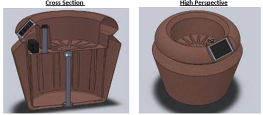
In order to better understand the design process, two design obstacles will be presented with their associated solutions. The first major design challenge was how to remove the pump and other electronics during the winter season. Our initial designs called for a four inch diameter tube to start at the base of the planter and travel upward just below the level of the soil. The tubing would rest just below the soil’s surface level. Once the winter months came the cap would be accessible and the pump would be removed via the tube. Although this design would have worked, it certainly was not the cleanest or most user friendly solution. As a result, Mike proposed that the planter actually be two separate pieces (a top piece and bottom piece) that were put together after the manufacturing process. This can be seen in the ‘Cross Section’ picture below. The ‘two piece’ approach has other less obvious benefits. Maintenance, cleaning, and drainage of the planter (via a plug in the bottom) all become very simple tasks if the lid can be removed. Another major design obstacle was incorporating a rectangular solar panel into a circular planter, while maintaining an aesthetically pleasing design. A number of design iterations were necessary, but the team eventually created a solar panel that had the ability to “sink in” to the planter (see the ‘high perspective’ image).
OBJECTIVE 2:
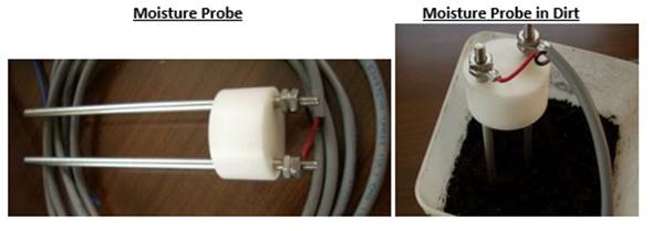
In order to make the product commercially viable, it was of great importance to have a low cost yet reliable moisture probe. As discussed in the Phase I report, the development team tested numerous “off the shelf” low cost sensors tested. Although these sensors provided a general sense of wet and dry, they were not highly accurate nor were they durable over long term deployments. Once the Phase II grant was approved, a portion of the funds went toward developing a custom moisture probe with two objectives. First was to reduce the per-unit manufacturing cost. Second was to improve the accuracy over the probes used in Phase I. After doing preliminary research it became clear both were possible. The general design included the use of two stainless steel rods (stainless steel does not corrode), approximately 5 inches in length, held together at the top and separated by approximately 1 inch of plastic material (see “Moisture Probe” image below). Once the prototype was built, weeks of testing were necessary to calibrate the probes.
The science behind the probe is relatively simple and uses measurements from both probe ends to determine the overall moisture level of the soil. A voltage (5 Volts) is sent through the first probe end. The device then measures the voltage on the second probe end. The difference in voltage between the two probe ends allows the device to determine the volumetric water content of the soil. For example, if the soil is completely dry there is no way for the electricity to travel from one probe to the next, therefor the voltage on the second probe would be around zero Volts. However, if the soil was completely wet, the electricity would be able to travel through the liquid and the voltage would be around three Volts (if they were connected by copper you would see around 5V). Finally, if the soil was somewhat moist, you would expect around two Volts. By testing the voltage on the second probe over various moisture levels, a moisture curve can be created giving an expected voltage per the soils volumetric water content. There are two more variables which affect the results. First is the salinity of the water (can be influenced by fertilizers). As more salt enters the water, electricity begins to flow easier through the liquid and therefor affects the results. Second is the density of the soil. For example, if the soil is moist and dense electricity will flow easier than if the soil is moist and loosely packed. In the end, the custom moisture probe cost approximately four dollars and had sufficient accuracy for certain applications.
While the custom moisture probe described above gave the development team the ability to create a product for low cost applications where a high level of accuracy is not necessary, a solution still was needed for high precision/high cost applications. The development team was able to find a moisture probe that is highly accurate, insensitive to salinity, and will not lose accuracy over time. The cost per probe is approximately $40 and will be used for high-end applications. The testing of this probe is described in the following section.
OBJECTIVE 3:
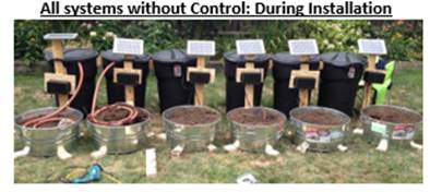
The majority of our testing was performed in Illinois. As a result, the prototypes were deployed in the summer as the region’s temperature increased. The experiment included a control planter, to be watered manually, and six other planters watered entirely by the Waterbelly systems. The planters were numbered 1 to 6 (see “All systems without Control: During Installation” image below). Planter numbers 2 - 6 utilized a timer (in addition to the moisture probe) to control the pump time, therefor guaranteeing five gallons per pump. The timer also prevented the pump from being activated twice within a 48 hour period to prevent overwatering. Planter 1 was controlled entirely by the moisture probe. The function of the moisture probe in all six Waterbelly systems was to measure the moisture level in relation to the “dry point.” The dry point is the level of volumetric water content at which the moisture probe signals that the pump should turn on; this value varied for planters 2 – 6. A dry point value of ‘4’ was chosen for planter # 1 (In doing so system 4 acted as a control for system 1). Throughout the summer, data was collected to determine which planters were watered on which day, and how much water was used. Once the growing season is over the data can be interpreted for the final report. Based off of plant health as well as water usage, our team aims to determine the optimal “dry point” to maintain plant life while limiting water usage.
Future Activities:
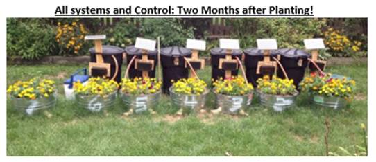
In order to achieve positive environmental and economic impacts through reductions in water usage, carbon emissions, and maintenance costs the Waterbelly product needs to be one that is financially viable, rigorously tested, highly accurate and durable. With the assistance of Mike Elwell, our team was able to create a visually striking planter that solved all design obstacles during the nine month re-design period. Additionally, the design incorporates a 60 gallon holding tank which will reduce planter maintenance costs and associated vehicles emissions by up to 91.66 percent. One of the components that allows for this technology is a highly accurate moisture probe for only $40, whose value and accuracy was confirmed through months of prototype testing. Although the final results will not be available until the National Design Expo, the Waterbelly system has produced healthy plants through circuit controlled water regulation (see “All systems and Control: Two Months after Planting!”). The final objective mentioned was a move toward commercialization. While this is an ongoing process, our team is happy to announce, as of August 2012, the first sale of Waterbelly technology to a Conservation District in central Illinois!
Supplemental Keywords:
cost benefit, water, carbon dioxide, design for environment, moisture probe, resource recovery, solar powerRelevant Websites:
Progress and Final Reports:
Original AbstractP3 Phase I:
Solar Powered Water Collection, Containment, and Self Regulating Distribution System | Final ReportThe perspectives, information and conclusions conveyed in research project abstracts, progress reports, final reports, journal abstracts and journal publications convey the viewpoints of the principal investigator and may not represent the views and policies of ORD and EPA. Conclusions drawn by the principal investigators have not been reviewed by the Agency.