
Grantee Research Project Results
Final Report: Selective Source AC/DC Power Supply
EPA Grant Number: SU836040Title: Selective Source AC/DC Power Supply
Investigators: Kimball, Jonathan , Wright, Charles , Patnaik, Abhishek , Kashyap, Amshumaan Raghunatha , Rayachoti, Anagha , Irigoyen, Alberto Berrueta , Ahmadi, Reza
Institution: Missouri University of Science and Technology
EPA Project Officer: Hahn, Intaek
Phase: I
Project Period: August 15, 2011 through August 14, 2012
Project Amount: $14,430
RFA: P3 Awards: A National Student Design Competition for Sustainability Focusing on People, Prosperity and the Planet (2011) RFA Text | Recipients Lists
Research Category: Pollution Prevention/Sustainable Development , P3 Awards , P3 Challenge Area - Air Quality , Sustainable and Healthy Communities
Objective:
The objective of this project is to develop a power conversion system suitable for supplying power to both ac and dc loads simultaneously from both ac sources, such as the power grid, and dc sources, such as a photovoltaic (PV) panel. PV panels are naturally dc, as are many loads, such as computers. A conventional power conversion system converts the PV output to ac for grid intertie (e.g., 240 V, 60 Hz, single-phase), which then must be converted to low-voltage dc (e.g. 24 V dc) to power loads. With the proposed converter, both dc and ac loads are supplied by either PV power, when available, or the grid, otherwise. This will increase system efficiency.
Summary/Accomplishments (Outputs/Outcomes):
Modern residences contain a diversity of load types. Conventional ac loads include incandescent and fluorescent lighting, appliances that use motors (refrigerators, washing machines, HVAC, etc.), and other high-power loads such as toasters and hair dryers. Most electronic devices, although powered from 120 V ac, are actually dc loads that include internal power converters. Examples include cell phone chargers, LED lighting, and computers. In fact, a major limiting factor for the acceptance of LED lighting is the power conversion necessary between 120 V ac and low-voltage dc. Most future load growth will be in these dc-type loads, because conventional loads are either being replaced (incandescent → fluorescent → LED) or are becoming more efficient.
Fig. 1 shows the proposed power converter architecture. A maximum power point tracking converter (MPPT) ensures that the PV panel operates at its optimal conditions. A dual active bridge (DAB) converter provides bidirectional power flow between a low-voltage dc bus and a high-voltage dc bus. Bidirectional flow allows dc loads to be powered from the grid or ac loads to be powered from the PV panel, depending on solar conditions and load levels. A power factor correction (PFC) converter draws high-quality power from the grid, and an inverter converts the high-voltage dc power into 120 V ac for conventional ac loads.
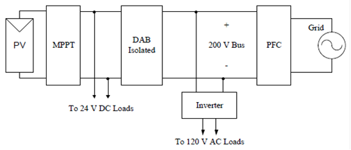
Fig. 1. System electrical architecture, in block-diagram form.
At this time, all elements of the power converter have been simulated, both independently and together. Some subsystems have been experimentally verified. The most complete experimental results are available for the DAB converter.
Fig. 2 shows experimental results for the DAB. The primary objective of the DAB is to regulate the low-voltage dc bus (24 V). In Fig. 2(a), load suddenly decreases, and the DAB effectively regulates the voltage, with a settling time of approximately 300 ms. Fig. 2(b) shows zoomed-in waveforms of normal operation.
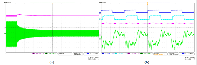
Fig. 2. Experimental results for DAB converter; (a) response to a load step (decrease from 203 W to 57 W), where upper trace is low-voltage bus and lower trace is secondary-side transformer current at 200 ms/div; (b) normal operation, traces from top are gate command on high-voltage side, gate command on low-voltage side, low-voltage bus, and secondary-side transformer current, 20 μs/div.
Figs. 3-4 show the simulated system behavior for the complete power conversion system. The sequence is:
- t = 0: nominal load on all terminals, but only the PFC converter is switching
- t = 0.1 s: inverter and DAB are enabled
- t = 0.5 s: step increase in the PV output power
- t = 0.75 s: step increase in the ac load current
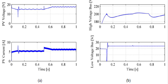
Fig. 3. Simulation of integrated system, (a) MPPT action on PV panel, (b) DAB regulation of low-voltage bus.
Fig. 3(a) focuses on the MPPT, Fig. 3(b) shows the two dc buses, and Fig. 4 shows the ac input and output waveforms.
Short-term tasks for Phase I include building and testing the remaining subsystems, integrating the complete system, and testing the system with a PV panel. With a functioning system, efficiency will be evaluated and improvements will be implemented.
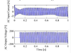
Fig. 4. AC terminals, grid side input current and inverter output voltage, for full system simulation.
Conclusions:
The fundamental approach is sound. Further testing is required to validate the efficiency gain. However, all subsystems interact effectively and support a diversity of loads and sources. This new approach has the potential to broaden adoption of PV technology in both the developed world (on-grid) and the developing world (off-grid or unreliable grid).
Supplemental Keywords:
photovoltaic, solar energy, dc-dc, maximum power point trackingRelevant Websites:
Missouri S&T Solar House Team Exit
The perspectives, information and conclusions conveyed in research project abstracts, progress reports, final reports, journal abstracts and journal publications convey the viewpoints of the principal investigator and may not represent the views and policies of ORD and EPA. Conclusions drawn by the principal investigators have not been reviewed by the Agency.