
Grantee Research Project Results
Final Report: Design of a Low Cost, Self Operating Hydraulic Ram Pump for Water Retention and Lifting in Developing Countries: Bringing Clean Water to Haiti
EPA Grant Number: SU835077Title: Design of a Low Cost, Self Operating Hydraulic Ram Pump for Water Retention and Lifting in Developing Countries: Bringing Clean Water to Haiti
Investigators: Engel, Bernard A. , Ahiablame, Laurent , Kujur, Birendra , Deak, Brian , Poppe, Brooke , Garner, Leah , DeNardo, Nick
Institution: Purdue University
EPA Project Officer: Hahn, Intaek
Phase: I
Project Period: August 15, 2011 through August 14, 2012
Project Amount: $15,000
RFA: P3 Awards: A National Student Design Competition for Sustainability Focusing on People, Prosperity and the Planet (2011) RFA Text | Recipients Lists
Research Category: Pollution Prevention/Sustainable Development , P3 Awards , P3 Challenge Area - Safe and Sustainable Water Resources , P3 Challenge Area - Sustainable and Healthy Communities , Sustainable and Healthy Communities
Objective:
The overall goal of this project is to help alleviate clean water problems in Haiti. The specific objectives of this project are to: (1) design low cost hydraulic ram pumps based on available prototypes; (2) conduct a comprehensive feasibility study for the product installation; and (3) implement the proposed design in communities in Haiti. These objectives will be accomplished by a team of interdisciplinary engineering students through Engineering Projects in Community Service and Global Engineering Program (GEP) Design Teams. During Phase I of this project, a group of students from the team is traveling to Haiti to install two prototypes and conduct an in country feasibility analysis in collaboration with the North Haiti Christian Mission. The purpose of the trip is to collect site information in order to improve the design, build improved prototypes, and install these during a subsequent visit.
Summary/Accomplishments (Outputs/Outcomes):
Background
Hydraulic ram pumps have been used for over two centuries in many parts of the world before the widespread use of the electrical power and the internal combustion engine. Known as hydram or impulse pumps, a hydraulic ram pump is a device which serves to lift water with no other external energy source (Taye, 1998). In other words it uses energy in water (head or velocity) to lift water. A hydram device uses the energy created from low head water as the driving force to pump a portion of this water to a head that is much higher than the supply head. Because water flows continuously in the stream, the hydram also operates continuously as the direct result of the water head energy. Hydraulic ram pumps are generally simple devices that consist of two moving parts (the waste valve and delivery valve), an air chamber and an air valve (Taye, 1998). Hydrams operate by the opening and closing of the waste and delivery valves. When the waste valve closes, a high pressure rise is created in the drive pipe and the air valve allows air into the hydram to replace the air absorbed by the water due to the high pressures and mixing in the air chamber. It should be noted that the role of the air chamber is to maintain the continuity of the pumped water flows.
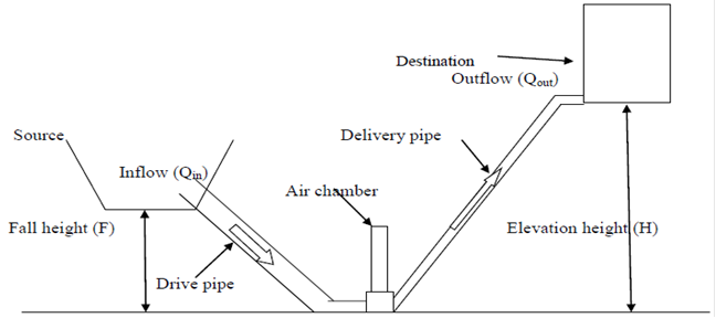
Figure 1. Conceptual Schematic of Ram Pump installed in a feasible location
Design and Improvement of the Hydraulic Ramp Pump
During Phase I, different prototypes were made and were tested. The theoretical calculations and experimental testing resulted in an improved design and a final prototype that is economically feasible and more efficient than earlier designs. Figures2a and b show the final prototype which costs approximately $100.00 to construct, excluding the inlet and outlet pipes. A major criterion and advantage of this design was that the different parts of the pump should be easily available for purchase with no additional manufacturing requirement. Moreover this final prototype (Figure 1) is designed in a way that it can easily assemble without prior high crafting skills.
Specifications of the Hydraulic Ramp Pump Prototype
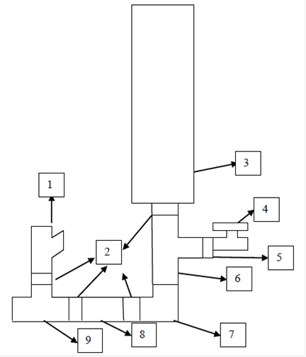
| Number | Size | Part name |
| 1 | 1 -1/2 inch | Brass Waste valve |
| 2 | 1-1/2 inch | Threaded Connector |
| 3 | D – 3 inch, H – 24 inch | PVC air chamber |
| 4 | ¾ inch | Stop valve |
| 5 | 1-1/2 to ¾ inch | Coupler |
| 6 | 1-1/2 inch | Tee |
| 7 | 1-1/2 inch | 90 degree elbow |
| 8 | 1-1/2 inch | Brass spring valve |
| 9 | 1 -1/2 inch | Tee |
Table 1. Schematic of the final prototype with its components
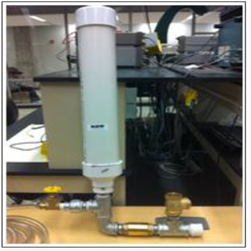
Figure 2. Final prototype of the hydraulic ramp pump designed to be implemented in Haiti
It is very important to have the spring valve and the waste valve made of metal (for longer life cycle) because these two parts are actively engaged when the pump is operating. Based on our testing results, it appears that the efficiency of the ram pump depends on following factors:
- Drive pipe length: The drive pipe has a minimum and maximum allowable length to maximize the efficiency of the pump. This will limit bursting of the drive pipes due to high pressure. The minimum length of the pipe should be 150 times its diameter, and the maximum length should be 1,000 times its diameter.
- Air chamber size: The size of the air chamber has to be chosen in a way that the frequency of the compression and expansion of air inside the chamber (modeled as a spring mass system) is in close range with the frequency of the water hammer.
- Waste valve: The waste valve cross-sectional area should not exceed the drive pipe cross-sectional area. Also the waste valve should be always oriented perpendicularly to the water flow direction in order to achieve maximum efficiency for the pump.
Efficiency Test
The efficiency of the pump depends on the relationship between F/H and Qin/Qout(see Figure 1). In order to determine the efficiency of the prototype, two sets of experiments were conducted. First, Qin/Qout was kept constant while F/H varied. Second, F/H was kept constant with varying Qin/Qout.
The efficiency of the ram pump can be defined as the ratio of heads at the output to the input as described in the following equation:
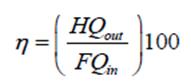
where F is the fall height; H is the elevation height; Qin is the volumetric flow rate at the inlet; and Qout is the volumetric flow rate at the outlet. During the first experiment, an efficient performance was attained with 32.2 L/min for Qin, 4.2 L/min for Qout, and Qin/Qout was7.67. During the second experiment, the fall and elevation heights were kept at 1.4 m and 5 m, respectively, which gave F/H ratio of 0.28. Other factors such as the length of the pipe, its position and orientation are not included in this experiment, but will be investigated in Phase II.
Results from the experiments show that the efficiency of the pump increases with increase in fall/elevation ratio (Figure 3), while the efficiency decreases with decrease in Qin/Qout(Figure 4). These results are specific to the prototype presented in this study. Perhaps the efficiency may vary if another pump size is used.
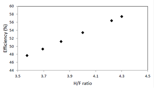
Figure 3.Efficiency versus fall height/elevation height ratio
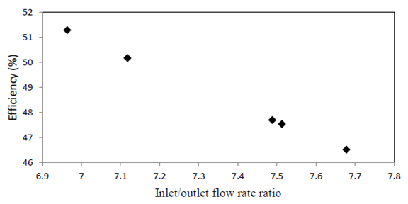
Figure 4.Efficiency versus Inflow/Outflow ratio
Project team members visited the project partner in Haiti the week of March 12 (the week the report and proposal were due) to implement the prototype ram pumps. Thus, details of the implementation were not available at the time of the report preparation.
Supplemental Keywords:
clean water, hydraulic ram pump, Haiti, pumpThe perspectives, information and conclusions conveyed in research project abstracts, progress reports, final reports, journal abstracts and journal publications convey the viewpoints of the principal investigator and may not represent the views and policies of ORD and EPA. Conclusions drawn by the principal investigators have not been reviewed by the Agency.