
Grantee Research Project Results
Final Report: Low Temperature Stirling Engine for Waste Heat Recovery from Distributed Power Sources
EPA Contract Number: EPD11045Title: Low Temperature Stirling Engine for Waste Heat Recovery from Distributed Power Sources
Investigators: Weaver, Samuel P
Small Business: Cool Energy Inc.
EPA Contact: Richards, April
Phase: I
Project Period: March 21, 2011 through September 19, 2011
Project Amount: $79,096
RFA: Small Business Innovation Research (SBIR) - Phase I (2011) RFA Text | Recipients Lists
Research Category: SBIR - Green Buildings , Small Business Innovation Research (SBIR)
Description:
Cool Energy, Inc. (CEI) has identified several waste heat recovery (WHR) candidates whose waste heat could be recovered and converted to electric power using one or more of CEI’s 20 kWe Stirling engines. The primary applications are those in which the waste heat is present the highest percentage of time, in order to maximize the benefit generated by the economic investment. Operational information has been collected for coffee roasting machines, glass firing kilns, and diesel generators, among other waste heat sources. Although the 20 kWe design electric power output objective was chosen to be an aggressive but achievable jump beyond CEI’s current experience with 2 and 3 kWe Stirling engines, some of these applications very clearly could use even larger engines, or an array of 20 kWe engines. The initial proposal for this SBIR project had a 25 kWe design size, but subsequent to the proposal and based on customer feedback, CEI has decided to offer models of 10, 20, and 40 kWe in scale, and focused work under this project on the 20 kWe design. The design process includes looking at multiple candidate engine configurations, selecting the most optimal layout, and then determining the best performing operating speed, component sizing, and component materials. Methods used include Stirling engine numerical simulations, heat recovery system simulation, and computer-aided design.
Summary/Accomplishments (Outputs/Outcomes):
CEI evaluated three initial Stirling engine designs, each producing 20 kWe electric power output, using CEI’s Stirling engine analysis program. The first had a 55 cm heat exchanger and regenerator diameter (all equal to each other and hereinafter called the canister diameter), with non-metallic film structure for the regenerator. The other two had 35 cm canister diameters, one with non-metallic film and the other with stainless steel foil for the regenerators. The 55 cm canister diameter engine was considered impractically large. Further analysis was conducted on the two 35 cm canister diameter engines for performance, speed and cost, resulting in down-selecting the polyimide film regenerator version. This engine layout was configured to fit into a pressure vessel having a diameter comparatively smaller than the length, resulting in a four-Stirling cycle, V-8 cylinder arrangement. Optimal designs of this engine layout were computed for each of three standard pressure vessel diameters, for each of 25 design operating speeds ranging from 600 to 1200 rpm. A 36-inch outside diameter pressure vessel was ultimately chosen, having the best balance between cost/size and thermal efficiency. An optimum design operating speed of the engine then was determined, based on improved models for the thermodynamic and transport properties of the nitrogen working fluid and CEI’s piston ring design and dynamic simulation models. Because of reliability concerns about the piston rings operating at high velocities within the cylinders, the speed was chosen to be 600 rpm, to keep this velocity low. Specifications for the waste heat recovery heat exchanger were developed in complete thermal detail. Specifications for a representative hot gas waste heat stream temperature of 400°C and the mass flow rate necessary to power one 20 kWe Stirling engine at 300°C were chosen to submit to heat exchanger manufacturers for quotation. Operation protocols and ancillary hardware for plant balance were made similar to CEI’s existing designs.
Conclusions:
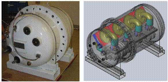
Figure 2. Photo of Cool Energy P3 3 kWe Stirling engine prepared for testing (left); CAD model of 20 kWe Stirling engine designed during SBIR Phase I (right).
The perspectives, information and conclusions conveyed in research project abstracts, progress reports, final reports, journal abstracts and journal publications convey the viewpoints of the principal investigator and may not represent the views and policies of ORD and EPA. Conclusions drawn by the principal investigators have not been reviewed by the Agency.