
Grantee Research Project Results
Final Report: Chemical Doser for AguaClara Water Treatment Plants
EPA Grant Number: SU834752Title: Chemical Doser for AguaClara Water Treatment Plants
Investigators: Weber-Shirk, Monroe , Swetland, Karen A. , Patel, Akta , Lion, Len , Higgins, Matthew , Guerrero, Christopher , Salwen, Adam , Kendrot, Jordanna , Owusu-Adarkwa, Frank
Institution: Cornell University
EPA Project Officer: Page, Angela
Phase: II
Project Period: August 15, 2010 through August 14, 2012
Project Amount: $75,000
RFA: P3 Awards: A National Student Design Competition for Sustainability Focusing on People, Prosperity and the Planet - Phase 2 (2010) Recipients Lists
Research Category: Pollution Prevention/Sustainable Development , P3 Awards , P3 Challenge Area - Safe and Sustainable Water Resources , Sustainable and Healthy Communities
Objective:
Accurate chemical dosing in water treatment plants is imperative to ensure optimal efficiency during flocculation, sedimentation, filtration and disinfection. AguaClara designed the linear chemical dose controller (LCDC) to allow plant operators to reliably set and maintain a desired dose of coagulant and disinfectant without the help of computers or pumps. A linear relationship between head loss and chemical flow is created by using the major head loss through a small diameter tube to control the flow. To maintain this linear relationship, the systems have been designed to eliminate sources of minor head loss. Our team is actively working to minimize minor head losses through the systems, reduce the systems' maximum percent error and standardize the components and calibration techniques to be used to fabricate the systems in the field.
Summary/Accomplishments (Outputs/Outcomes):
AguaClara is a program based out of Cornell University that designs and builds sustainable, municipal-scale water treatment facilities without electricity. All technologies developed through AguaClara are designed to be operator friendly, easily constructed and maintained, and cost effective. Continuous, accurate chemical dosing is an essential part of AguaClara plant function as it ensures effective flocculation, sedimentation, filtration and disinfection. Chemicals that must be added at different points during the water treatment process are coagulant (PACl or Alum may be used) and chlorine. The linear chemical dose controller (LCDC) is a device that the facility operator can use to directly set doses of coagulant and disinfectant based on the flow rate into the facility. It is one of the many technologies that is currently providing reliable chemical dosing to six of the eight facilities already in operation in Honduras. A LCDC in one of the most recent plants in Alauca is shown in Figure 1. When used in conjunction with a linear flow orifice meter, the system is semi-automated only requiring that the operator set the dose based on influent turbidity.
Correct chemical dosing is the single most important requirement for day to day operation of drinking water treatment plants. The failure of mechanized chemical pump systems is widespread from Kathmandu to Tegucigalpa. The chemical dose controller provides a simple, robust, highly reliable method to dose chemicals.
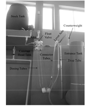
Figure 1. LCDC in a newly constructed facility in Alauca, Honduras.
System Design Theory
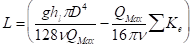
The LCDC is designed to provide accurate chemical doses for water treatment using the resistance provided by friction. Total frictional head loss through a pipe can be described by the sum of the Hagen-Poiseuille equation and the minor loss equation:
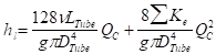
where head loss (hl) is a function of the diameter (DTube) and length (LTube) of tubing, viscosity of the liquid (n), sum of minor loss due to expansions (Ke) and flow rate (QC) through the pipe. Major losses can be seen in the left term and minor losses in the right term. Since minor losses introduce nonlinearity in the system, minimizing this term results in a linear relationship between head in the system and flow rate assuming all other parameters remain constant. In practice, significant minor losses were introduced by using connecting fittings slightly smaller than tube inner diameters at the entrance and exits and coiling the dosing tube. To correct for this, barbed fittings slightly larger than tube inner diameters are used and a counter weight is applied to the coiled tubes to minimize curvature.
Given that viscosity could be an influential parameter and that it would be beneficial for operators to change stock concentrations, a Vibro Viscometer was used to confirm the kinematic viscosity of varying concentrations of coagulant. For the range of concentrations currently used by AguaClara facilities, the change in viscosity was small enough to be accounted for by decreasing tubing length.
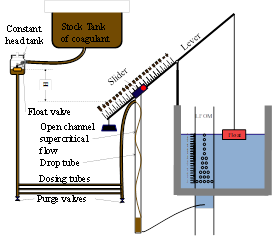
A schematic of the LCDC in Figure 2 shows the major system components and the state of the system at no flow through the treatment facility. When flow begins to fill the entrance tank, the float rises, rotating the lever arm and creating a difference in head (H) between the top of the water level in the constant head tank and dosing tube outlet (Figure 2(a)). The float valve in the constant head tank maintains the depth of chemical in the tank. For the hypothetical situation during no flow though the plant (Figure 2(b)), H becomes zero and no chemical is dosed.
a
Figure 2. Schematic of LCDC and major system components when (a) water is flowing through the plant and (b) with no flow through the plant.
Documentation, Calibration and Standardizing
In order to make the LCDC reproducible and accurate, a design algorithm, calibration techniques and standardized components were compiled. The design algorithm is used to produce a range of possible tubing lengths and diameters from which the user can choose a final design. Equations were derived from the Hagen-Poiseuille and specific minimize sizes to reduce minor head loss. The design algorithm is below:
1. Calculate the maximum flow rate through each available dosing tube diameter that
keeps error due to minor losses below 10%.
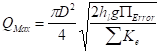
2. Calculate the total chemical flow rate that would be required by the treatment system
for the maximum chemical dose and the maximum allowable stock concentration.
3. Calculate the number of dosing tubes required if the tubes flow at maximum capacity.
4. Calculate the length of dosing tube(s) that correspond to each available tube diameter.
5. Select the longest dosing tube that is shorter than the maximum tube length allowable
based on geometric constraints.
6. Select the dosing tube diameter, flow rate, and stock concentration corresponding to
the selected tube length.
A comprehensive list of standardized parts was also created that indicates which parts change with design specifications and which properties make the chosen parts appropriate for the LCDC. This helps accommodate for the fact that the locations where the plants are being built might not have access to the exact specified commercial parts.
Step by step, operator -friendly calibration techniques that minimize flow rate error have been developed and tested. This allows for each new system to be setup and used with confidence to the operator. Calibration of the LCDC has two main steps. First, the system must be calibrated to the situation where there is no flow of water into the entrance tank, and thus no dose administered by the LCDC. This sets the difference in head between the water height in the constant head tank at the same height of the dosing tube. Then each incremental flow rate is set and marked on the lever arm.
With the entire system setup and calibrated, experiments were performed to determine the performance of the system based on the calibration techniques and standardized parts list developed. The results, shown in Figure 3, indicate that the LCDC performs within an acceptable range of accuracy. At larger flow rates, actual flow deviates only slightly from theoretical flow through the dosing tubes.
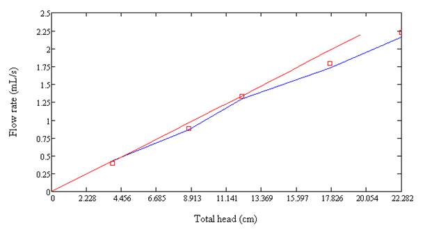
Figure 3. Flow rate as a function of head for a LCDC constructed using calibration techniques and standardized parts. Red line indicates theoretical flow while the blue line shows experimental values.
Conclusions:
A linear chemical dose controller has been built, tested, refined and documented for widespread use in water treatment plants. These dosers are already in use in AguaClara facilities and plant operators routinely rely on these dosers to perform without fail even when the plant operates unattended for hours. Creating a reliable chemical dose controller that can automatically adjust for variations in plant flow rate has been a major accomplishment of the AguaClara team.
Journal Articles:
No journal articles submitted with this report: View all 4 publications for this projectSupplemental Keywords:
coagulation, flow control, flow measurement, municipal water treatment, gravity poweredRelevant Websites:
Progress and Final Reports:
Original AbstractP3 Phase I:
Dose Controller for AguaClara Water Treatment Plants | Final ReportThe perspectives, information and conclusions conveyed in research project abstracts, progress reports, final reports, journal abstracts and journal publications convey the viewpoints of the principal investigator and may not represent the views and policies of ORD and EPA. Conclusions drawn by the principal investigators have not been reviewed by the Agency.