
Grantee Research Project Results
Final Report: Ocean Wave Energy Harvester with a Novel Power Takeoff Mechanism
EPA Grant Number: SU835734Title: Ocean Wave Energy Harvester with a Novel Power Takeoff Mechanism
Investigators: Zuo, Lei , Ai, Junxiao , Liang, Changwei , Li, Xiaofan , Wise, Adam , Lee, Rosaline , House, Evan , Boontanom, Jedhathai , Capindo, Carl Matthew , Mizrahi, Coby , Palencia, Gabriel , Fernandez, Luis , Sim, Duncan , Heyde, Keith , Ding, Josh
Institution: Virginia Tech
EPA Project Officer: Hahn, Intaek
Phase: II
Project Period: August 15, 2014 through August 14, 2016
Project Amount: $90,000
RFA: P3 Awards: A National Student Design Competition for Sustainability Focusing on People, Prosperity and the Planet - Phase 2 (2014) Recipients Lists
Research Category: P3 Challenge Area - Air Quality , Sustainable and Healthy Communities
Objective:
The aim of Phase II was to complete manufacture of the prototype MMR and buoy, and then to test it in lab and in an ocean environment. That was followed by completion of a more thorough dynamical analysis of the system, design of an advanced control, design of power electronics and energy storage, and then integration of the system and demonstration of the improved design. With this proposed project, we hope to foster progress toward sustainability by achieving the mutual goals of economic prosperity, protection of the planet, and improved quality of life for its people –people, prosperity, and the planet – the three goals of the EPA P3 program.
Summary/Accomplishments (Outputs/Outcomes):
Figure 1 shows the assembled power takeoff system. Two racks are connected by two plates from top and bottom respectively. The pinion, one way bearing, gearbox are connected with a C shaft. A bearing house is designed to align the pinion and one way bearing with gearbox and generator. As the outer diameter of the one way bearing is larger than the outer diameter of pinion, an adaptor was used to connect them. After studying into different types of gearbox, we’ve finally chose GHP-22 for our project, which is a 1:5 ratio gearbox. The diameter of the pinion is 0.075m. The generator is a three phase permanent electromagnetic machine (GL-PMG-500A) of 500 watts rated at 450 rpm. The internal resistance of each phase is 0.235W. For this prototype, only one side is designed with generator and gearbox. Another generator will be installed symmetrically in the future. The assembled buoy, power takeoff and overall system is shown in Figure 2.
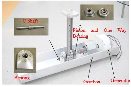
Figure 1. Assembled power takeoff system
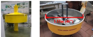
Figure 2. Assembled overall system. This photo only shows one generator installed in the power takeoff system. Another generator can be installed symmetrically.
Lab testing for the power takeoff mechanism was also conducted to verify the model of mechanical motion rectifier. The test set up is shown in Figure.3(a). The power takeoff system is fixed on the frame of the test machine with four rods while the racks are connected with the grips at the bottom. The racks are driving by the grips with a sinusoidal displacement input. The circuit used in the experiment is shown in Figure.4(left). The voltage of the external resistance is measured as output. We did two groups of experiments. One is the MMR system, while the other one is non-MMR system for comparison. Only one gear is used in non-MMR system to drive the shaft as shown in Figure.3 (b). The generator used in the experiment is a 500W three phase generator (model number: GL-PMG-500A). The parameters of the generator we used here are Ri=0.235Ω(phase resistance) and ke=0.795V/(rad/s)(voltage constant). The radius of the pinion is r=0.0375m. The gear ratio of the gearbox is 1:5.
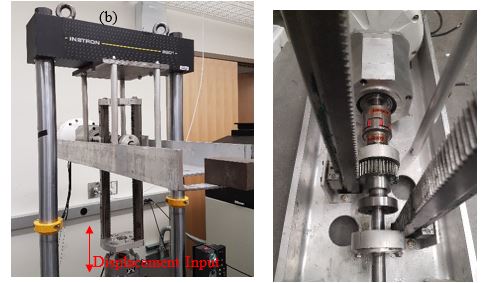
Figure 3.Test setup and the non-MMR system used in the experiment.
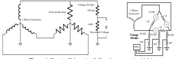
Figure 4. Circuit of lab testing (left) and ocean testing (right)
where, in Eq. , and ,
- ωgeis the rotation speed of the generator.
- vinputis the speed of the rack, which is the same as the drive speed of test machine.
- ngis the gear ratio of the gearbox, which is 5 in the prototype.
- ris the radius of pinion, which is 0.0375m.
- ωge_0is the rotation speed of generator at the moment of disengagement.
- ceand meis the equivalent mass and equivalent damping of the system, me≈110kgin the calculation.
- Vpis the phase voltage.
- Riand Reare the internal and external resistance. The internal resistance Ri=0.235Ω.
- keis the voltage constant of the generator, which is ke=0.795V/(rad/s).
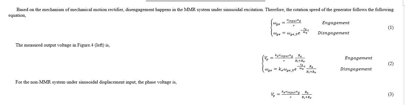
One should notice that we are using a three phase AC generator in the experiment. Therefore, the predicted results of the voltage shown in Eq. and is the envelope of the experimental data. More details about three phase AC generator can be found in [74].
Figure.5 and Figure.6 plots the predicted and experimental results of output voltage of MMR system and non-MMR system under sinusoidal displacement input. The external resistor is 2Ωin
Figure.5 and 10Ωin Figure.6. One can find that in Figure.5 and Figure.6, the predicted voltage envelope is close to the experiment results for both MMR system and Non-MMR system. When Re=2Ωin Figure 16, the disengagement is not significant due to the large external damping. When Re=10Ωin Figure 17, the model predicts the disengagement and engagement very well. This results validates our model of MMR system. In addition, the efficiency of MMR system and non-MMR system is also compared under various driving condition in Figure.7, Figure.8 and Figure.9. The efficiency of MMR system is around 5%-15% higher than non-MMR system depending on the test condition.
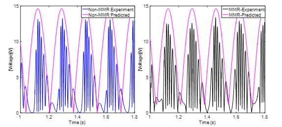
Figure 5. Absolute value of the phase voltage for non-MMR system and MMR system. For the results shown in this figure, the input amplitude is 10mm with a frequency of 3Hz. The external resistance is Re=2Ω.
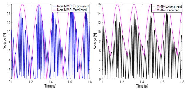
Figure 6. Absolute value of the phase voltage for non-MMR system and MMR system. For the results shown in this figure, the input amplitude is 10mm with a frequency of 3Hz. The external resistance is Re=10Ω
Figure 7.Efficiency comparison of MMR system and non-MMR system in the bench test. For the results shown in this figure, external resistance Re=1Ω. The driving amplitude from the test machine is 5mm.
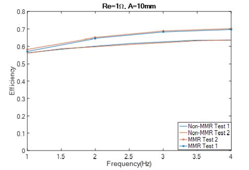
Figure 8.. Efficiency comparison of MMR system and non-MMR system in the bench test. For the results shown in this figure, external resistance Re=1Ω. The driving amplitude from the test machine is 10mm.
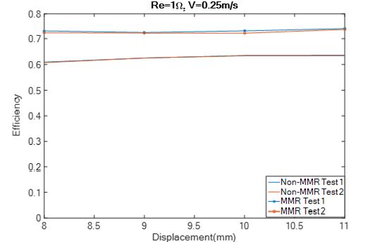
Figure. 9 Efficiency comparison of MMR system and non-MMR system in the bench test. For the results shown in this figure, external resistance Re=1Ω. The amplitude of the driving velocity in this figure is 0.25m/s for all the curves.
One should notice that typical wave period is around 5-10s and the amplitude of wave height can be a couple of meters. This means the PTO system moves in low frequency with high amplitude in real application. The maximum stroke length of the test machine is 40mm, which is much smaller than typical wave amplitude. Therefore, it is impossible for us to simulate wave motion with current test machine. However, the amplitude of driving velocity as shown in Figure.9 is 0.25m/s, which falls in to the range of typical particle velocity (0.2-1.5m) in real case. On the other hand, one can find that the efficient of these two system does not change much if the amplitude of driving velocity is constant. Therefore, the experiment results is still useful for real application.
After some small modification in machine shop, the ocean testing was conducted in Long Island Sound, NY. Figure.10 shows the supplies used in this experiment. Figure.10(a) is the research vessel Seawolf (Figure.10a) rented from the SBU School of Marine and Atmosphere; (b) is the boom used to fix the prototype as shown in Figure.10 (c) and (d) are the assembled prototype.
The experiment location was at the middle of long island sound (Figure.11a). A tensioning weight of 80kg was used at the end of the boom to provide a reaction. As shown in Figure.11 (b), the upper shaft was attached to the bottom of the tensioning weight. An extension wire was used to connect a circuit (Figure.11 (c), (d)). The current and voltage were recorded with DAQ.
From NOAA’s Buoy Station 44039 (41°8'15" N 72°39'17" W), the wave height was 0.2m and dominated wave period was 4s. Figure.12 shows the recorded current and voltage and output power from one of the three phases of the generator. The peak of the output power in one phase is 205W while the average power is only 21W. Totally 63W average power was generated from the three phases. Such a number is less than the rated power in the concept design. There are several reasons: (1) The wave condition in long island sound was very small on the experiment day (significant wave height is 0.2m.) (2) The parameters of the power takeoff system were not well tuned (3) The energy was actually extracted through the relative motion between the buoy and the research vessel. The disengagement happens at the non-zero troughs in the zoomed Figure.12(b). The ocean wave test does verify the feasibility of harvesting the power from the wave motion with mechanical motion rectifier.
Environment Impacts
We looked into the environmental impacts of our point absorbers. The first potential environmental concern for point absorbers is their vertical structure and the physical space they take up. These vertical structures take up physical space, which can be a problem for travelling schools of marine life. Many species of marine life travel along one path throughout the ocean to reach the same destination each year, either to travel for mating season, or to give birth in shallower waters, where there are fewer predators. If a large farm of point absorbers is built in the path of these travelling schools, it could potentially pose issues, even resulting in the schools unable to reach their intended destinations, which could result in lower populations of said animal. Additionally, it is hypothesized that a large farm of point absorbers could endanger marine life from large currents and magnetic fields being created in the electrical generation. Currently there are no scientific studies that support the claim that electrical or magnetic fields pose a health risk to living creatures, and some studies even refute the idea, suggesting that electrical and magnetic fields are harmless to the overall health of animals. Despite this, several species use magnetic fields for navigation, such as the Salmon, which uses magnetic fields to find its breeding grounds each year. A large farm of point absorbers could produce enough conflicting magnetic fields that a school’s migration would be interrupted. This concern, however, is minimal in the current stages of ocean energy technology.
Another potential environmental concern with point absorbers is the added structures could provide a home for species such as clams, sea weeds, corals, and other bio-foul to grow on and breed. Whether this is a negative effect or a positive effect is still being debated, but it is a concern that should be considered, especially for mechanical success. If a point absorber has many moving parts, or is finely balanced, the added life growing on it could present problems, such as interfering with moving parts, or tipping the structure either completely over or on an axis that will decline efficiency. There are some that argue that allowing these species to grow on the point absorbers increases bio-diversity, which can be beneficial or detrimental to a system. Increasing bio-diversity in a habitat is beneficial cause it increases the resistance of the biome, as allows endangered or declining species more room to rehabilitate. Increased bio-diversity can also be a detriment to a habitat, as it can shift the delicate balance of niches in the habitat. Species that are not native to that area, but were carried in ocean currents and allowed to grow on the point absorber, could consume more food, harming the species already present. Any species growing on a point absorber would have to be monitored and evaluated for environmental effects.
Aside from those two environmental concerns, point absorbers present few other possible issues. There is some concern with lubricants used in a point absorber, Lubricants used to keep the moving parts from rusting, or oils used in the hydraulics of the system, run the possibility of leaking into the ocean, which will most likely cause harm to local fauna. The lubrication required for any system, however, would be minimal and well under the EPA’s standards of oil pollution. Point absorbers are one of the most common designs of wave energy devices because they are energy efficient while posing few and manageable environmental concerns. Other wave energy designs are energy efficient, however they pose greater risks to the environment, and to the populace in general.
Conclusions:
In this project, the design, fabrication and test of a single body wave energy converter with mechanical motion rectifier is presented. The floating buoy is designed as a 46 inches cylinder with cone top and bottom. The power takeoff system is based on the rack pinion system combining with a pair of one-way bearings which can convert the bidirectional input rotation into unidirectional output rotation. The detailed design and fabrication for both floating buoy and power takeoff system are presented. The mathematic model of the mechanical motion rectifier is established with Lagrange method. The model is verified with the bench test results. The bench test also shows that the efficiency of MMR system is higher than that of non-MMR system due to disengagement. The ocean test of the prototype is also presented and the total average power can be 75W (215W in peak) in real waves with a significant height of 0.2m and dominated wave period of 4s.
Journal Articles:
No journal articles submitted with this report: View all 2 publications for this projectProgress and Final Reports:
Original AbstractP3 Phase I:
Ocean Wave Energy Harvester with a Novel Power Takeoff Mechanism | Final ReportThe perspectives, information and conclusions conveyed in research project abstracts, progress reports, final reports, journal abstracts and journal publications convey the viewpoints of the principal investigator and may not represent the views and policies of ORD and EPA. Conclusions drawn by the principal investigators have not been reviewed by the Agency.