
Grantee Research Project Results
2014 Progress Report: Passive Unitized Regenerative Fuel Cell (PUReFC) for Energy Storage in Off-grid Locations
EPA Grant Number: SU835288Title: Passive Unitized Regenerative Fuel Cell (PUReFC) for Energy Storage in Off-grid Locations
Investigators: Fabris, Drazen , Krishman, Shoba
Current Investigators: Fabris, Drazen , Lele, Sandeep , Sizemore, Michael , Krishnan, Shoba
Institution: Santa Clara University
EPA Project Officer:
Phase: II
Project Period: August 15, 2012 through August 14, 2014 (Extended to August 14, 2015)
Project Period Covered by this Report: September 1, 2013 through September 1,2014
Project Amount: $89,023
RFA: P3 Awards: A National Student Design Competition for Sustainability Focusing on People, Prosperity and the Planet - Phase 2 (2012) Recipients Lists
Research Category: Pollution Prevention/Sustainable Development , P3 Challenge Area - Air Quality , P3 Awards , Sustainable and Healthy Communities
Objective:
Objective: Develop a portable, autonomous, and unitized regenerative fuel cell capable of providing continuous, sustainable energy to meet demands in off-grid applications. When coupled with a photovoltaic cell, the system will manage energy supply and demand to ensure uninterrupted renewable power. The regenerative fuel cell leverages innovative capillary wicking structures for simplified and efficient performance.
Description: An estimated 1.6 billion people lack access to electricity. This project will offer a viable means to supply clean, reliable power to off-grid locations. The Passive Unitized Regenerative Fuel Cell (PUReFC) is an energy storage device being developed as a substitute for electro-chemical batteries. During peak hours of solar insolation, photovoltaic panels will provide power for electrolysis—generating hydrogen and oxygen. When needed the device will generate electricity from hydrogen and oxygen source tanks to provide power. The research work aims to develop a fuel cell design that features a porous polymer wicking structure to transport water to and from the membrane without the need for additional active water management.
Desired Results: The first generation prototype design (2011-2012) suffered measured performance decay during sustained operation as well as observed anode water flooding. Second generation prototype development focused on redesigning the overall system, improving the capillary wicking structures and the contact with the water storage structure, developing the manufacturing process, as well as refining the gas sealing system. The system will be re-evaluated on efficiency, output, power density, and price competitiveness during the extension period.
Progress Summary:
The findings of this report primarily focus on the design and fabrication of an improved prototype with passive water management. Based on analysis and observation of first generation prototype operation, the revised design/fabrication approach implements a shorter transport distance within the porous wicks as well as a two-stage gas sealing design. A new fabrication methodology aims to improve interfacial contact between porous domains and provide better control over porous polymer structure resolution.
First Generation Prototype Additional Testing: As a means to determine aspects of design that required review, additional transient discharge testing was conducted for the first generation prototype. These data present general trends of long term performance stabilization at the expense of reduced power output (Figure 1). The current density curves in Figure 2 initially exhibit a stage of rapid current density rise as the membrane electrode assembly (MEA) re-hydrates.
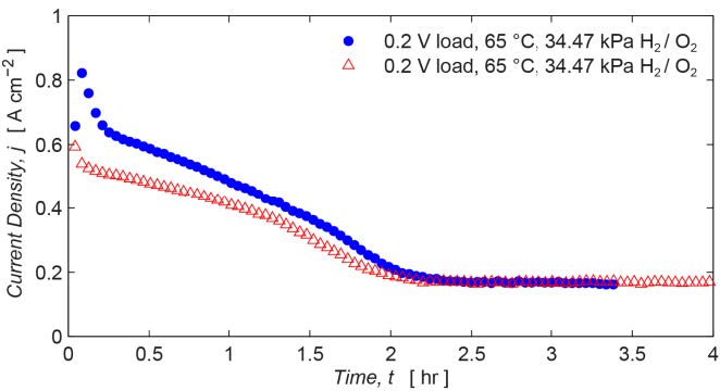 | 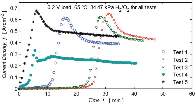 |
| Figure 1. First generation prototype transient discharge testing at 0.2V loading. | Figure 2. First generation prototype transient discharge testing at 0.2V loading. |
This is consistent with the relationship between MEA water uptake and proton conductivity1. It is hypothesized that the current density degradation that follows the initial current rise is associated with flooding of the cathode gas diffusion layer (GDL). The hydrophilic GDL saturates, which increases gas transport resistance—resulting in a reduced reaction rate.
 |
| ||||
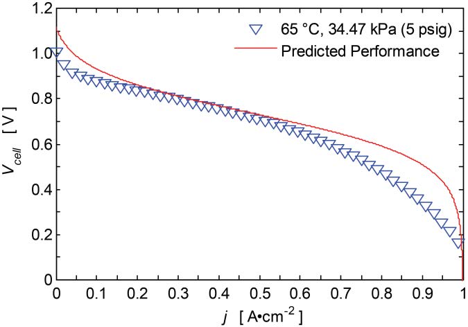
| Figure 3. First generation prototype discharge polarization curve (~10 min span). | Table 1. Selected calculation values for equilibrium water partial pressure differential across the MEA at 0% initial anode relative humidity. |
This fits well with measured discharge polarization curves in which GDL saturation causes additional concentration loss at higher current densities (Figure 3). The data indicate that water transport rates within the porous wicks were insufficient. Ideally, the passive management should prevent GDL/channel flooding while still leaving enough water at catalyst sites for oxygen reduction to continue.
For sustained operation, balancing the rate of back-diffusion with the rate of electro-osmotic drag is critical. To identify equilibrium water partial pressure values that match back-diffusion to electro-osmotic drag, the water rate balance was calculated for various operating current densities. Low values of equilibrium partial pressure differentials (ΔPeq) presented in Table 1 are further indicators that insufficient water removal will quickly result in back-diffusion overcoming electro-osmotic drag—leading to cell flooding.
Second Generation Design/Prototype: The radial design of the first generation prototype, with flow channels diverging from a central inlet port, resulted in a large range of wick transport lengths (1.5-12 mm). In this layout, the pressure gradient through the wicks was largely driven by the gas flow in the channels. During dead-ended operation (non-recirculating gas), flow within the channels is dictated by the reaction rate—resulting in very low flow rates. In this case, water transport mostly stagnates in the longer wicks due to an insufficient driving pressure gradient.
Figure 4. Second generation PUReFC prototype assembly.
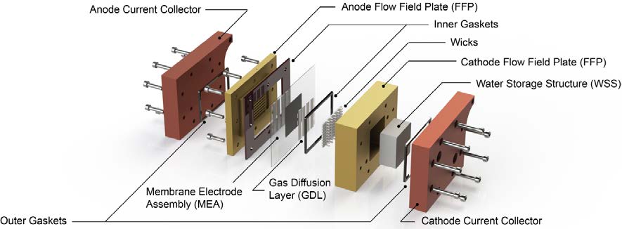
The second generation Passive Unitized Regenerative Fuel Cell (PUReFC) design primarily seeks to reduce the wicking transport distance to approximately 3 mm. The new design also ensures that all the wick transport lengths are uniform across the cell active area. The prototype has a 5 cm2 active area and 1 mm deep by 1.2 mm wide parallel gas channels, and contains both inlet and outlet ports for each reactant gas allow for operation either in a non-recirculating or a recirculating mode. The inclusion of outlet ports should improve the purging and conditioning process. Double-sided machined components as well as a two-stage seal are incorporated into the design. In this arrangement, gaskets are used to seal against a metal surface with the MEA sandwiched in between. An inner gasket prevents oxygen leakage by sealing against the anode (H2) flow field plate (FFP), while an outer seal prevents hydrogen leakage by sealing against the cathode (O2) FFP. The two-stage design eliminates the need for perfect alignment of hydrogen and oxygen gaskets during assembly. For easier complete cell assembly, two sub-assemblies are used: an inner assembly including both FFPs, gaskets, gas diffusion layers (GDLs), and the MEA, assembled firs; an outer assembly consisting of copper current collector plates and additional gaskets.
The key feature of the design is the coupling of the porous polymer wicks within the cathode FFP to a porous Water Storage Structure (WSS) which acts as a storage reservoir for water generated from discharge operation. The capillary pressure gradient across these two porous domains is designed to be the primary driver of water transport.
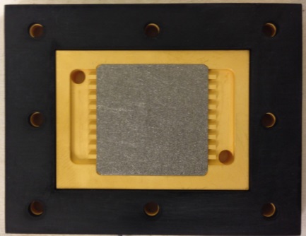 | 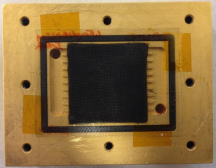 | 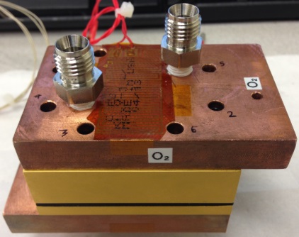 |
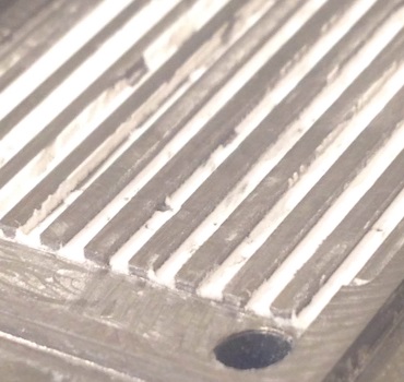
| Figure 5. Gold-coated titanium anode FFP. A sintered titanium GDL is installed above flow channels. An EPDM outer gasket seals H2, with the MEA sandwiched in between it and cathode FFP. | Figure 6. Gold-coated titanium cathode FFP. The MEA is installed above the sintered titanium GDL and inner EPDM gasket. The gasket seals O2, with the MEA sandwiched in between it and the anode FFP. | Figure 7. Fully assembled second generation PUReFC prototype. Copper current collector plates with inlet and outlet ports are shown at top and bottom. |
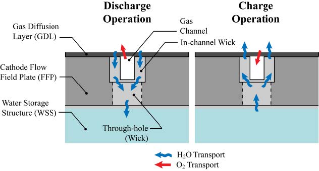 | 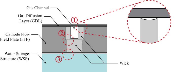 | |
| Figure 8. New passive water management operational schematic (cross section shown). The surface of the gas transport channels is coated with the porous polymer wick structures and through-holes are machined and filled with porous polymer wick between the channels and a Water Storage Structure (WSS). | Figure 9. Three critical contact areas between different porous domains (cross section shown) are identified. Poor interfacial contact at any of the three contact areas can lead to insufficient water transport through the system. |
The wicks are fabricated from 2-hydroxyethyl methacrylate-co-ethylene dimethacrylate (HEMA-co-EDMA) using a UV lithographic method. A porous polyvinyl alcohol (PVA) sponge is used for the WSS; the WSS is housed in a cavity underneath the FFP channels. Short through-holes filled with HEMA-co-EDMA act as hydraulically conductive vias that connect the in-channel wicks and the WSS. Water produced at cathode catalyst sites moves downwards during discharge operation and upwards during charge operation. The new design also seeks to eliminate issues of poor interfacial contact by incorporating a large contact area between the porous polymer and WSS. This is a thin region of polymerization on the back side of the flow field plate (Figure 9).
Porous Polymer Fabrication: The uncontrollability of HEMA-co-EDMA polymerization makes fabrication of high resolution (1 μm) structures challenging. Initially, a methodology similar to the process used by Strickland et al.2 was attempted.
In this procedure, an ultra-thick UV-transparent SU-8 photoresist mold (~800 μm) was independently fabricated before the porous polymer fabrication. Using this component along with a quartz bottom sealing plate, the base monomer solution could be injected into the FFP volume and exposed to UV from top and bottom.
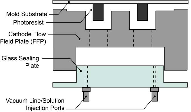 |  |
| Figure 10. Porous polymer fabrication assembly showing an expanded view of the mold (~800 μm photoresist) and glass sealing plate. A top mold limits in-channel polymerization to desired regions. The glass sealing plate extends partially into the depth of the WSS chamber, allowing room for a thin interfacial layer (200 μm) of HEMA-co-EDMA. | Figure 11. Preliminary attempt at mold release method using ~100 μm SU-8 features. Mold release achieved using N2 pressurization. |
 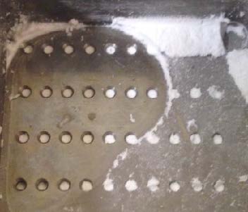 | 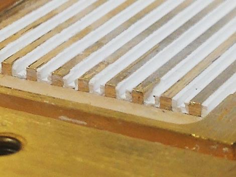 |
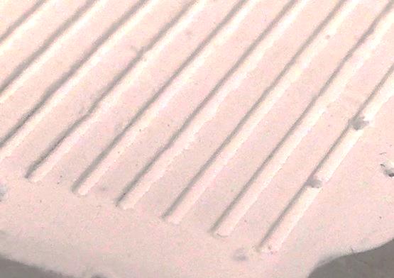
| Figure 12. In-channel porous polymer wicks produced using the SU-8 mold (Top); through-hole porous polymer wicks on the backside (Bottom). | Figure 13. In-channel porous polym |
The bottom sealing plate extends only partially into the depth of the WSS cavity—leaving a thin gap (~200 μm) for fabrication of an intermediary layer of porous polymer (Figure 9).
Before producing a viable SU-8 mold for use in this procedure, a preliminary attempt was conducted to determine feasibility of the technique. Promising results using ~100 μm SU-8 features (Figure 11) prompted further characterization of mold fabrication. SU-8 layer thickness was characterized using angled, high-resolution optical microscopy. After using SU-8 molds with controlled feature height, the resulting porous polymer wicks were fabricated along the channel walls and filled the through-holes (Figure 12).However, release of the mold and bottom sealing plate proved difficult. A large portion of the fragile wicks was delaminated upon removal of these components. Delamination issues and poor control over structural resolution are indicators that the SU-8 methodology can be improved further. As such, the PUReFC prototype was prepared for testing using another process. As a compromise, the HEMA-co-EDMA was produced to occupy the full volume of the gas flow channels and carefully machined to create the intended geometry (Figure 13).
Conclusions:
Second Generation Design/Prototype: The second generation prototype has been designed and its components fabricated based on observations/analysis of the first generation prototype. The new design implements a shorter transport distance within the porous wicks as well as a two-stage gas sealing design and improvements in the pressurization and purging system.
Porous Polymer Fabrication: The newly designed passive management layout was successfully fabricated. After initial attempts using an SU-8 mold were unsuccessful, careful machining was effective in producing the porous polymer consistent with the original geometry (Figure 8).
Future Activities:
Porous Media Characterization: A comprehensive set of pore characterization measurements are being conducted on the HEMA-co-EDMA and PVA. Pore size analysis and permeability testing have been outsourced to Porous Materials Inc. in Ithaca, NY.
proton exchange membrane fuel cell (PEMFC), unitized regenerative fuel cell (URFC), photovoltaic (PV), fuel cell energy systems, energy storage, renewable energy, innovative technology, pollution prevention, environmental sustainability, Passive Unitized Regenerative Fuel Cell (PUReFC), polymer wicking structure: Discharge and charge operating performance of the second generation PUReFC prototype will be characterized at a variety of operating conditions (e.g. temperature, pressure, and duration). Control case tests (without polymer wicks) will be conducted to determine the significance of performance improvement.
Journal Articles:
No journal articles submitted with this report: View all 4 publications for this projectSupplemental Keywords:
proton exchange membrane fuel cell (PEMFC), unitized regenerative fuel cell (URFC), photovoltaic (PV), fuel cell energy systems, energy storage, renewable energy, innovative technology, pollution prevention, environmental sustainability, Passive Unitized Regenerative Fuel Cell (PUReFC), polymer wicking structureProgress and Final Reports:
Original AbstractP3 Phase I:
Regenerative Fuel Cell for Off-Grid Renewable Energy Storage | Final ReportThe perspectives, information and conclusions conveyed in research project abstracts, progress reports, final reports, journal abstracts and journal publications convey the viewpoints of the principal investigator and may not represent the views and policies of ORD and EPA. Conclusions drawn by the principal investigators have not been reviewed by the Agency.