
Grantee Research Project Results
Final Report: AguaClara's Ram Pump for Zero Electricity Drinking Water Treatment
EPA Grant Number: SU839463Title: AguaClara's Ram Pump for Zero Electricity Drinking Water Treatment
Investigators: Weber-Shirk, Dr. Monroe , Nathans-Kelly, Dr.Traci M , Hunter, Payton , Ju, Alyssa , Pang, Ching , McCann, Maile , Storch, Alycia , Tsang, Cheer
Institution: Cornell University
EPA Project Officer: Page, Angela
Phase: I
Project Period: December 1, 2018 through November 30, 2019
Project Amount: $14,999
RFA: P3 Awards: A National Student Design Competition Focusing on People, Prosperity and the Planet (2018) RFA Text | Recipients Lists
Research Category: P3 Awards , P3 Challenge Area - Air Quality , P3 Challenge Area - Safe and Sustainable Water Resources , P3 Challenge Area - Sustainable and Healthy Communities , P3 Challenge Area - Chemical Safety
Objective:
AguaClara Cornell is a multidisciplinary engineering team based at Cornell University that develops sustainable water treatment technology. The AguaClara plant design is gravity-powered, electricity-free, and scalable to fit the needs and size of any community. A subteam of AguaClara Cornell is developing the AguaClara Vertical Ram Pump (ACVRP), and inline zero waste pump that utilizes the energy in flowing water to pump a portion of that water to a higher elevation. While a conventional ram pump wastes the water used for energy extraction, the ACVRP allows this water to continue to the plant’s storage tank to then be distributed for use by the community. The ACVRP will be implemented in AguaClara plants to pump clean water up to storage tanks that hold water for the plant plumbing and diluted chemicals for chemical dosing of the water. Currently, the transportation of water up to the storage tanks is a burden placed on the plant operators. The team is currently working to improve the design of the ACVRP to increase efficiency and ease of use as well as perform experiments to gain a better understanding of the physics behind the ACVRP and how to make adjustments to improve performance.
Summary/Accomplishments (Outputs/Outcomes):
Force Analysis and Ideal Spring Constant
Efficiency of the ACVRP is defined as the percentage of theoretical flow rate that is actually achieved. The theoretical flow rate is calculated based on dimensions and terminal velocity while the actual flow rate is measured experimentally. In order to optimize the efficiency of ACVRP, a range of ideal spring constants is needed to supply the optimal forces to open and close the valve of the pump as shown by the positions in figure 1, and therefore forces required to toggle the plate valve were calculated.
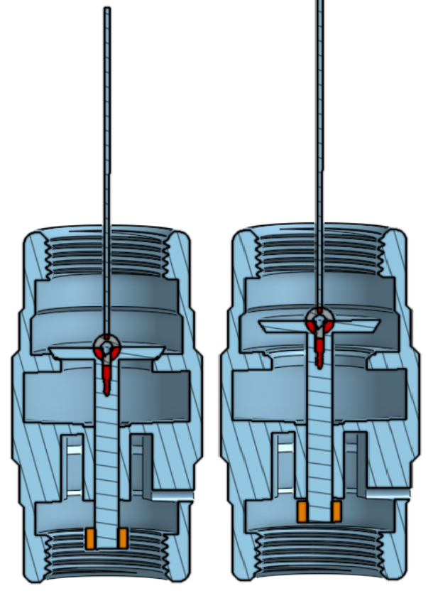
Figure 1: Plate open and plate closed position
The team developed a procedure for finding both of these forces. In order to find the maximum drag force on the plate, the team used a two pulley system connecting the plate valve with a bottle with water in it hanging from the pulley that extends out of the head tank. The amount of water in the bottle was adjusted until the plate was just opened. The weight of the bottle at this instant was equal to the force from the falling water in the drive pipe on the plate. In order to find the hydrostatic force, the height of the water column above the plate was found and the hydrostatic pressure from this height of water was calculated. This pressure was multiplied by the area of the plate to find the force acting on the plate.
Using the determined forces, a range of ideal spring constants were etermined. Since Hooke's Law depends on the compression length, delta x of k^1 was defined as an intrinsic material property of the spring dependent on the actual length of the spring rather than its compression length, such that Hooke's Law could be written as:
F=((k^1)x)/L where k’ = kL
Even though the design of the system has changed since these experiments and calculations were performed, this work will inform the team in the future on how to find the desired forces for the new system. The same calculations would be applied for finding the intrinsic k constant for extension springs, and since separate springs are used for keeping the plate opened and closed, calculations should account for two spring constants and their respective changes in length.
Redesigning the System
Ease of Adjustment:
The redesigned spring system addresses the issue of difficult readjustment of the ACVRP and implements a method that involves minimal deconstruction of the mechanism. The previous design required a check valve at the lower end of the system to be dismantled in order for the compression spring to be adjusted or replaced. This series of actions to make changes to the ACVRP is tedious and often difficult` to perform in the conditions that the pump was installed and operates in. The main challenge that hindered adjustment of the pump was that while the mechanism was in operation most of the adjustable parts were submerged. The team created a design that allowed for instantaneous adjustment of the spring constants, while the system is in operation.
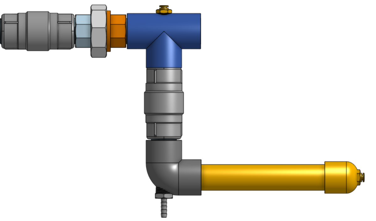
Figure 2: Overview
This new system involves three external extension springs instead of one internal compression spring. The three external springs are hooked onto three separate threaded eyebolts, which can be moved up or down to adjust the forces being applied on the plate within the lower check valve.
All three springs are attached to a bottom plate that serves to transmit this upward force through a metal wire rope, to the plate in the check valve as shown in figure 1. The eyebolts that the springs are connected to are secured by two nuts each to a stationary top plate that restricts the springs from falling into the drive pipe. The two outer springs on the design are longer springs with a low spring rate to apply a constant upward force while the plate is oscillating through its cycle. The current inner spring has a higher spring rate compared to the outer springs in the system to account for the increased pressure when the plate is “closed'' in the check valve. It is attached to its eyebolt with a piece of metal wire that has slack in it when the plate is in the open position. As the plate closes, the wire is pulled, the middle spring extends and, thus, exerts an upward force on the plate. This allows the forces corresponding to the open and closed positions to be adjusted individually. This spring system is stationed above the flowing water and is easily accessible in order to raise or lower the effective force transmitted by the springs. Changing the force of the check valve plate is now easier to accomplish because of the greater accessibility to the force applying springs and the greater range of adjustment available.
The support structure of the new spring design also has an adjustable height component as a way to make the replacement of springs of various sizes easier. Because of this design the metal wire connected to the check valve plate does not need to be replaced when springs are changed in height, rather the support height can be changed to accompany the necessary spring length.
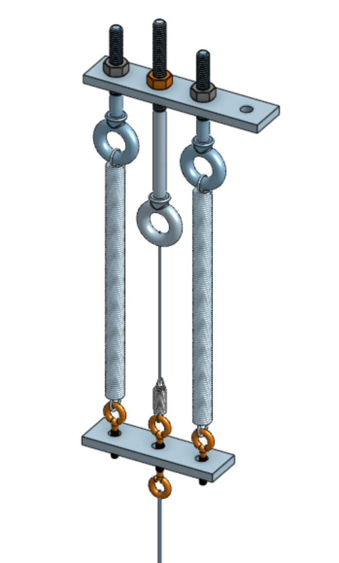
Figure 3: Lab Apparatus
During the period of funding, the research team fabricated a new experimental apparatus for the testing of the ACVRP. The apparatus had to be shorter so that the adjustment mechanism, which is now at the top of the apparatus, could be easily accessed. The design, similar to the previous one, involves a head tank, drive pipe, collection tank, waste valve, sump pump, air chamber and other smaller components. An aspect that differs in this lab setup is the addition of a throttle valve on the pipe that pumps water up to the head tank. Currently the team only has a sump pump that is able to pump water at one speed, so being able to adjust the flow rate of the water going into the head tank allowed for a faster and more controlled flow of water. The addition of a throttle with an on/off valve allowed the team to make a one-time adjustment to the flow rate that controls the amount of head from the bottom of the ACVRP to the top of the water while still having the ability to close this pipe when needed. This helped keep the calculated head level constant and made determining the necessary spring force for the opened and closed check valve plate more precise.
The new lab apparatus is also integrated into the team’s lab bench in order to reduce the amount of floor space occupied in the shared laboratory. The head tank is situated over the lab bench and pipes leading to the sump pump and collection tank are fitted through holes drilled into the lab bench. An 80-20 structure contains the head tank and fixes the whole structure to the team’s lab bench. The new apparatus was created mainly to consolidate the space in the laboratory and make a more compact model of the Ram Pump system.
Conclusions:
In the future, the team plans to develop a more refined design for the spring system. While the general three spring design has proven to work well, the team would like to iterate on this design to create an adjustment mechanism to replace the eyebolts. The new mechanism should be able to make very fine adjustments to the heights of the springs, move the two outer springs together, and be both robust and easy to use.
The team also plans to continue experimenting with how different adjustments of the springs affect the efficiency of the ACVRP. Since the three spring design is a recent change, currently little is known about how best to adjust the springs for optimal performance. The goal is to be able to develop an adjustment procedure that the plant operators can follow to ensure they are getting the maximum flow rate from their ACVRP.
Journal Articles:
No journal articles submitted with this report: View all 1 publications for this projectSupplemental Keywords:
Gravity-powered pump, hydraulic ram pump, AguaClara Vertical Ram Pump (ACVRP), drinking water treatment, plant plumbing; sustainable; green engineering; gravity; physics; accessible; economical; portable; zero waste; reuseP3 Phase II:
AguaClara's Ram Pump for Zero Electricity Drinking Water Treatment | 2021 Progress Report | 2022 Progress Report | Final ReportThe perspectives, information and conclusions conveyed in research project abstracts, progress reports, final reports, journal abstracts and journal publications convey the viewpoints of the principal investigator and may not represent the views and policies of ORD and EPA. Conclusions drawn by the principal investigators have not been reviewed by the Agency.