USER-FRIENDLY SOLAR OVENS FOR OUTDOOR AND INDOOR USE
Impact/Purpose:
The goal of this project is to develop safer and user-friendly solar ovens for indoor and outdoor cooking. Use sunlight for cooking has long been envisioned as an energy saving and clean technology that can greatly benefit people. Currently, solar ovens and solar cooking devices mostly use parabolic dish or trough reflectors to concentrate sunlight. It is often unsafe or unpleasant for people to access a cooker which stands at a focus point in front of a reflector. They can easily expose themselves to the concentrated sunlight accidentally. Blockage of sunlight by people moving around the concentrator is also disadvantageous for the receiver to get the maximum amount of sunlight. Therefore making a solar cooking device to be highly safe and user-friendly, and even capable of indoor use is the objective of this research.
Description:
A brief review of proposed work
This project was proposed to demonstrate a small scale solar cooking and heating system more applicable to home-scale, fast food or restaurant commercial use at low cost while considering the user’s safety. The phase I project is largely research oriented with the goal of illustrating and demonstrating such a possibility.
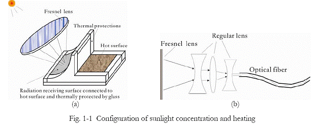
In the originally proposed design, a Fresnel lens is used to concentrate and cast sunlight on a receiving surface which is connected to a metal plate (serving as a hot plate), as shown in Fig. 1-1. The focus point of sunlight on the receiving surface is largely fixed. Except the small focus area the entire sunlight receiving surface and the hot plate can be thermally protected to prevent heat loss. Since heat loss is minimized and also the sunlight will not be interrupted by the person who cooks, it is expected that high safety and energy efficiency will be achieved in this system.
The hot surface as shown in Fig. 1 serves as an outdoor heating plate. When indoor heating is needed, optical fiber bundle was proposed to transmit concentrated sunlight into a house over a distance. The optical fiber bundle receives concentrated sunlight from one end, and at the other end the light comes out and cast on a target surface for heating.
Design-stage consideration of principles that benefit P3
The project is incorporated as a senior design project. Students in the team applied standard engineering design procedures in the project. This resulted in a list of the functional requirements and constraints defined in the design stage. As shown in Table 1-1, the team gave a considerable attention about how the project progress and how the developed prototype meet the requirement of benefiting people, planet, and the prosperity of a sustainable economy and environment.
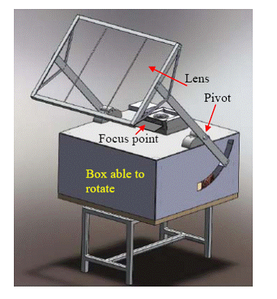
In the design, the team applied a two-freedom control scheme for the system to track the sunlight. First, the entire lens can be controlled to rotate in zenith direction about a pivot, as shown in Fig. 1-2. The distance between the lens and the pivot is just one focal length of the lens. Sunlight focus point is therefore kept always at the same height on the sunlight receiving plate. Seating on a rotating tray (Lazy Suzan), the box that holds the lens rotating system and the sunlight-receiving plate can rotate in azimuth direction. The combined control in azimuth and zenith directions can maintain the lens always facing the sun and focuses sunlight always on a point area on the receiving plate. The adjustment for tracking the sun can be manually controlled every few minutes by referring to a sundial attached to the arms which hold the lens. A sundial is an in-house-made simple device to indicate if a surface is right facing the sun. This low-cost, single-person manual control is particularly suitable to customers in developing countries. For customers in developed countries, both active and passive automatic controls for sun tracking are available for installation to the system at extra cost. A solar panel is considered to provide the electricity for this control.

In the design stage, cost-effective and sustainability is always incorporated as an important principle. Less-welding and more standard connecting and fitting parts were planned to be used in the system. This is designated to give convenience to people in less developed area for them to install and assemble the solar stove.
Figure 1-2 Design-stage image of the system (A protection shield between focus point and stovetop is not shown in the image.)
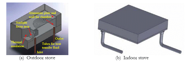
Following what was proposed of having an indoor cooking/heating function, a low-cost optical fiber bundle was tested prior to the design and fabrication for the optical system. This was also designated to verify the capability of optical fiber bundle in transmitting concentrated sunlight. Unfortunately the temperature of the plastic optical fiber bundle at the end that receives concentrated sunlight rose fast and even started melting very quickly. Although some glass optical fibers may tolerate high temperature, the cost is hardly acceptable in a solar cooking device targeting at home-scale and fast-food, or restaurant application. Due to the pursuit of a sustainable and cost-effective system, the original proposed indoor cooking using optical fiber bundle was not adopted in the final design. However, the pursuit of indoor cooking using solar energy was not given up by the team, instead, the new design considered pumping heat transfer fluid to transport heat from outdoor stove to indoor stove. This resulted in the special features of the outdoor and indoor stoves, as shown in Fig. 1-3. Both the outdoor and indoor stoves are essentially designed as fluid chambers (walls made of aluminum) that heat transfer fluid (at temperatures as high as 300 oC) can flow through. Heat transfer fluid from outdoor stove can be pumped to flow through the indoor stove when needed, which transfers heat for the purpose of indoor use. A small pump powered by electricity from a solar panel was considered. The heat transfer fluid in the chamber also helps to increase the heat capacity of the stove, which can run for about 10 minutes longer at sufficient high temperature if sun is temporarily hidden.

Fig. 1-3 The design-stage image of outdoor and indoor stoves
Fabrication, and test results
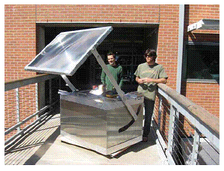
Mobility of the solar stove for outdoor use is considered by mounting casters on the bottom of the plate which holds the whole system. Light-weight and reduced use of expensive material in the system is also an important principle. Except the bearing and control for the rotating of lens, all other parts are made of aluminum. Students in the team carried out majority of the fabrication work based on engineering design and drawings made by the team. The partly-assembled system is shown in Fig. 1-4, which is a picture taken during a preliminary test. In the picture a shield between the cooking surface and the sunlight receiving surface was not shown.
Fig. 1-4 Partly-assembled solar cooking
Experimental work was conducted to test the temperature of the hot surface of outdoor stove and thus estimate the temperature of the heat transfer fluid in both the outdoor and indoor stove chambers. The outdoor stovetop takes about 18 minutes to reach a temperature of 100 oC (212 F) after started. In the morning, every 6 to 10 minutes the lens needs to be adjusted to track the sunlight. From noontime to around 3:00 pm, the time interval between two adjustments of the lens can be as long as 15 minutes. After that, it will be 10 minutes between two adjustments. The adjustment of lens can be easily done by referring to the sundial attached to the arm of the lens assembly.
The team directly used the outdoor stovetop and baked shrimps and meat successfully. A saucepot was also put on top of the stove surface, and it boiled water and vegetables. The feeling of using the solar stove is quite the same as like using a regular gas stove. This is an indication that the solar stove receives sufficiency energy for heating. The temperature of the stovetop was also measured during preliminary test. The temperature could reach 168 oC (334 F) at one of the side walls of chamber most far from the focus point. After implementation of a better thermal protection and black painting of the light-receiving surface, the temperature is expected to be 20-60 oC higher, and that will be sufficiently high for even deep frying.
Record Details:
Record Type:PROJECT(
ABSTRACT
)
Start Date:08/15/2008
Completion Date:08/14/2009
Record ID:
200884
Keywords:
SOLAR ENERGY, USER-FRIENDLY SOLAR OVEN, SUSTAINABLE DEVELOPMENT, CLEAN TECHNOLOGY, INNOVATIVE TECHNOLOGY, HEAT TRANSFER, THERMAL PROTECTION, OPTICAL SYSTEM, MULTI-DISCIPLINARY,
Related Organizations:
Role
:OWNER
Organization Name
:UNIVERSITY OF ARIZONA
Citation
:Tucson
State
:AZ
Zip Code
:85721
Project Information:
Approach
:Instead of reflective solar concentrators, large Fresnel lenses are to be used to concentrate solar light. Fresnel lenses manufactured using the state-of-the-art technology and material are thin, light weight, and cost effective. For outdoor cooking, the focused sunlight is casted on a heat dissipation metal block, which receives and conducts solar heat to a hot surface. The concentrated sunlight is effectively protected from exposure to people who operate and cook. Optical fiber cable is to be developed to transfer the concentrated sunlight into a house and provides heat to indoor cooking device. Strong sunlight will be well harnessed in such a process, and safety is assured. A capstone senior design team by six students from mechanical engineering and optical engineering will be formed to carry out the research, design, and prototype fabrication in the Department of Aerospace and Mechanical Engineering at the University of Arizona.
Cost
:$10,000.00
Research Component
:Pollution Prevention/Sustainable Development
Approach
:Instead of reflective solar concentrators, large Fresnel lenses are to be used to concentrate solar light. Fresnel lenses manufactured using the state-of-the-art technology and material are thin, light weight, and cost effective. For outdoor cooking, the focused sunlight is casted on a heat dissipation metal block, which receives and conducts solar heat to a hot surface. The concentrated sunlight is effectively protected from exposure to people who operate and cook. Optical fiber cable is to be developed to transfer the concentrated sunlight into a house and provides heat to indoor cooking device. Strong sunlight will be well harnessed in such a process, and safety is assured. A capstone senior design team by six students from mechanical engineering and optical engineering will be formed to carry out the research, design, and prototype fabrication in the Department of Aerospace and Mechanical Engineering at the University of Arizona.
Cost
:$10,000.00
Research Component
:P3 Challenge Area - Energy
Project IDs:
ID Code
:SU833914
Project type
:EPA Grant


